|
||
| Sulphuric Acid on the WebTM | Technical Manual | DKL Engineering, Inc. |
Knowledge for the
Sulphuric Acid Industry
![]()
Sulphuric Acid on the Web
Introduction
General
Equipment Suppliers
Contractor
Instrumentation
Industry News
Maintenance
Acid
Traders
Organizations
Fabricators
Conferences
Used
Plants
Intellectual
Propoerty
Acid
Plant Database
Market
Information
Library
Technical Manual
Introduction
General
Definitions
Instrumentation
Plant Safety
Metallurgial
Processes
Metallurgical
Sulphur Burning
Acid Regeneration
Lead Chamber
Technology
Gas Cleaning
Contact
Strong Acid
Acid Storage
Loading/Unloading
Transportation
Sulphur
Systems
Liquid SO2
Boiler Feed Water
Steam Systems
Cooling Water
Effluent Treatment
Utilities
Construction
Maintenance
Inspection
Analytical Procedures
Materials of Construction
Corrosion
Properties
Vendor Data
DKL Engineering, Inc.
Handbook of Sulphuric Acid Manufacturing
Order
Form
Preface
Contents
Feedback
Sulphuric Acid
Decolourization
Order Form
Preface
Table of Contents
Process Engineering Data Sheets - PEDS
Order
Form
Table of Contents
Introduction
Bibliography of Sulphuric Acid Technology
Order Form
Preface
Contents


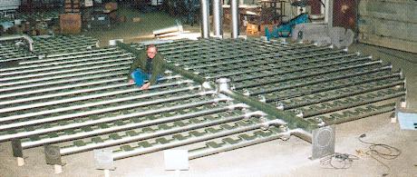
Strong Acid System - Acid
Distributors - Pipe Type Distributors
January 4, 2003
|
Introduction Materials of Construction |
Associated Links |
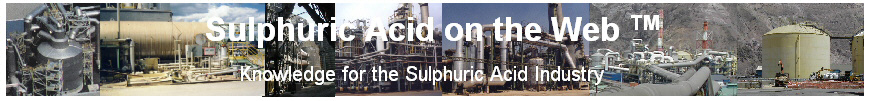
 Pipe
distributors, also known as ladder distributors, generally consists of one or
more main header pipes with smaller pipes or arms connected to the header(s) to
provide complete coverage across the tower cross-section.
The header and arms are generally flanged together to facilitate installation
and assembly as well as future dismantling for maintenance and cleaning.
Orifice or nozzles in the arms and header distribute the liquid into the tower.
Pipe
distributors, also known as ladder distributors, generally consists of one or
more main header pipes with smaller pipes or arms connected to the header(s) to
provide complete coverage across the tower cross-section.
The header and arms are generally flanged together to facilitate installation
and assembly as well as future dismantling for maintenance and cleaning.
Orifice or nozzles in the arms and header distribute the liquid into the tower.
Uniform liquid distribution in a pipe distributor is achieved by designing and operating the distributor with a high pressure across the orifices relative to the pressure drop in arms and header. To achieve the high pressure drop across the orifice requires a relatively high liquid velocity through the orifices. The liquid jetting out of the nozzle impacts against the nearest object creating significant amount of splashing.
Since the distributor is dependent on a minimum pressure drop across the orifice to achieve uniform distribution, the degree of turndown for a pipe type distributor is limited. This is generally not a problem except when the capacity of an existing plant is expanded and the acid flow to a tower is increased.
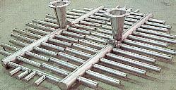
 To
prevent excessive splashing and subsequent entrainment of the liquid droplets,
the pipe distributor is generally buried under a layer of packing 300 to 600 mm
(12 to 24”). This results in one of
the major drawbacks of pipe type distributors.
The buried arms and headers reduces the cross-sectional area of the tower
available for gas flow. The
introduction of liquid at this point of reduced flow area causes localized
flooding and high pressure drop.
The solution is not to bury the distributor but the increase in splashing and
liquid entrainment overloads the downstream mist eliminators.
To
prevent excessive splashing and subsequent entrainment of the liquid droplets,
the pipe distributor is generally buried under a layer of packing 300 to 600 mm
(12 to 24”). This results in one of
the major drawbacks of pipe type distributors.
The buried arms and headers reduces the cross-sectional area of the tower
available for gas flow. The
introduction of liquid at this point of reduced flow area causes localized
flooding and high pressure drop.
The solution is not to bury the distributor but the increase in splashing and
liquid entrainment overloads the downstream mist eliminators.
Generally, the orifices are located in the lower half of the arms and headers generally 30°, 45°, or 90° from the horizontal. The lower half of the pipe is ideal for distributing the liquid down into the packing but the orifices are then prone to plugging by packing or brick chips. For any pipe type distributor an upstream strainer is a must to prevent plugging of the orifices. To minimize plugging of the orifices some distributors have been designed with the orifices drilled in the horizontal position with the belief that packing or brick chips will settle along the bottom of the pipe and not plug the orifices.
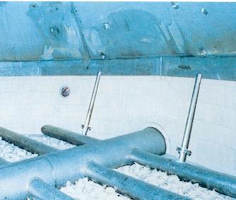
 An
advancement in the design of a pipe distributor is to locate the orifices in the
upper half of the pipe so the liquid is directed upwards and outwards from the
pipe. The liquid stream
impinges against a surface so the liquid is directed downwards in a fan shaped
stream. The energy of the liquid
leaving the orifice is dissipated against the surface of the target such that
the resulting fan shaped stream falls relatively gently to the packing surface
with minimal splashing. Designs of
this type of distributor have been done in both ductile iron and high silicon
stainless steel. In the case of
ductile iron distributors an acid resistant brick placed on top of the arms
serves as the target. In the
stainless steel pipe design a metal plate is the target.
The operation of this type of distributor requires a constant flow to the
distributor. Too high a flow
will result in an increase in splashing.
Too low a flow will affect the shape of the fan and hence the distribution of
liquid across the tower.
An
advancement in the design of a pipe distributor is to locate the orifices in the
upper half of the pipe so the liquid is directed upwards and outwards from the
pipe. The liquid stream
impinges against a surface so the liquid is directed downwards in a fan shaped
stream. The energy of the liquid
leaving the orifice is dissipated against the surface of the target such that
the resulting fan shaped stream falls relatively gently to the packing surface
with minimal splashing. Designs of
this type of distributor have been done in both ductile iron and high silicon
stainless steel. In the case of
ductile iron distributors an acid resistant brick placed on top of the arms
serves as the target. In the
stainless steel pipe design a metal plate is the target.
The operation of this type of distributor requires a constant flow to the
distributor. Too high a flow
will result in an increase in splashing.
Too low a flow will affect the shape of the fan and hence the distribution of
liquid across the tower.
|
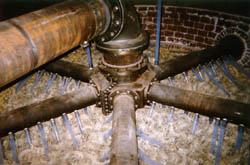
One drawback of pipe type distributors is the lack of uniformity of the distribution points. The location of orifices is limited to the location of the arms and headers which means that the space between the arms is not always effectively covered. Adding more orifices on the arms and headers increases the average number for distribution point per unit area but does not improve the uniformity of the coverage. One design overcomes this shortcoming in traditional pipe type distributors by using extension tubes to direct the liquid from each orifice to a specific location in the tower cross-section. In this particular design a ductile iron pipe distribution system is employed although stainless steel pipe could also be used. Orifices are drilled at specific locations and inserts with PTFE extension tubes are screwed into the pipe. The combination of the angle and length of extension tube allows the distribution point to be located precisely in the tower cross-section to achieve an overall uniform distribution pattern.
The advantage that a pipe distributor has over a trough distributor is its low cost. Basically, the distributor consists of pipe and flanges with holes drilled in the pipe. Compared to an alloy trough distributor a pipe type distributor contains less material and is easier to fabricate.
As previously mentioned, a pipe type distributor is prone to plugging of the orifice. This problem is partially addressed in some of the designs but plugging still occurs. In traditional designs the only way to clean out the plugged orifices is dismantle each of the arms and clean them out. This involves shutting down the plant, entering the tower, removing the packing covering the distributor, dismantling the arms, cleaning each one out and re-assembling the distributor. The procedure is time consuming and hazardous due to the presence of acid. One design that attempts to overcome this short coming extends the arms and headers into nozzles located in the side of the tower. When the blind flanges are removed from the nozzle, the interior of the distributors arms are revealed allowing them to be inspected and cleaned without entering the tower. Most of these maintenance problems can be avoided by using a properly designed and sized strainer upstream of the distributor.
Ductile iron has been and is still used for pipe type distributors. The material offers acceptable corrosion resistance against corrosion from the inside and outside of the pipe. There are several disadvantages associated with the use of ductile iron. The material is heavy requiring additional supports in the tower to support the weight of the distributor. Installation and maintenance of the distributor is more difficult because of the weight. The design is sometimes compromised due to the desired to use standard fittings in the design of the distributor. This may limit the designer to certain arm spacing, diameters and lengths. Since each piece is cast individually, custom parts are possible but add to the cost since new forms will be required.
Alloy pipe distributors offer excellent corrosion resistance, are light weight and easily fabricated. They allow the designer complete freedom to specify arm spacing, diameters and lengths.
PTFE nozzle inserts were sometimes used in ductile iron distributors. A relatively large hole (approximately 25 mm diameter) was drilled and tapped into the pipe and a PTFE threaded nozzle was inserted into the hole. The required orifice size was drilled into the PTFE insert. The high acid velocity through the orifice would quickly corrode an orifice drilled in the pipe so the PTFE offered better resistance against the high velocity acid. As well if the orifice size ever needed to changed it was a simple matter to replace the PTFE inserts.