|
||
| Sulphuric Acid on the WebTM | Technical Manual | DKL Engineering, Inc. |
Knowledge for the
Sulphuric Acid Industry
![]()
Sulphuric Acid on the Web
Introduction
General
Equipment Suppliers
Contractor
Instrumentation
Industry News
Maintenance
Acid
Traders
Organizations
Fabricators
Conferences
Used
Plants
Intellectual
Propoerty
Acid
Plant Database
Market
Information
Library
Technical Manual
Introduction
General
Definitions
Instrumentation
Plant Safety
Metallurgial
Processes
Metallurgical
Sulphur Burning
Acid Regeneration
Lead Chamber
Technology
Gas Cleaning
Contact
Strong Acid
Acid Storage
Loading/Unloading
Transportation
Sulphur
Systems
Liquid SO2
Boiler Feed Water
Steam Systems
Cooling Water
Effluent Treatment
Utilities
Construction
Maintenance
Inspection
Analytical Procedures
Materials of Construction
Corrosion
Properties
Vendor Data
DKL Engineering, Inc.
Handbook of Sulphuric Acid Manufacturing
Order
Form
Preface
Contents
Feedback
Sulphuric Acid
Decolourization
Order Form
Preface
Table of Contents
Process Engineering Data Sheets - PEDS
Order
Form
Table of Contents
Introduction
Bibliography of Sulphuric Acid Technology
Order Form
Preface
Contents


Materials of Construction - Ductile Iron
October 25, 2003
|
Introduction Manufacturing Pipe Fittings Quality Assurance Flanges Fittings Wall Thickness |
Associated
Links Grey Cast Iron |
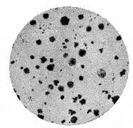
Photomicrograph or ductile iron at 100X magnification showing carbon in the form of nodules. |
Ductile iron derives its name from its ductility or bending ability whereas grey cast iron is more brittle. The difference between ductile and grey cast iron is their metallurgy. The presence of a closely controlled amount of magnesium causes the graphite to form as nodules rather than flakes.
A finer iron grain matrix is also formed in the surrounding ferritic structure. This change results in a material that is more ductile, stronger and tougher than regular grey cast iron.
Ductile iron exhibits the same corrosion resistance as regular grey cast iron but has the improved mechanical properties. Virtually all cast iron used in sulphuric acid service today is ductile cast iron. In the past, grey cast iron was used but after failures due to mechanical impact, ductile iron has become the industry standard.
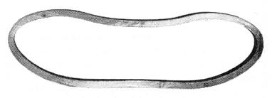
Ring section cut from 12" ductile iron pipe, which has been squeezed under hydraulic pressure to demonstrate that the material bends. |
Most cast iron pipe is centrifugally cast in water cooled metal moulds. The casting machine consists of a cylindrical metal mould mounted on rollers in a water jacket so it can be rotated at a relatively high speed. The entire rotating assembly is mounted on wheels so that it can be moved by means of a hydraulic cylinder. The hydraulic cylinder is supplied with a regulated amount of water at a constant pressure resulting in uniform longitudinal movement of the mould. Molten metal is fed into the centre of the mould through a trough that extends down the entire length of the mould. The trough ends in a spout that is directed to the side wall of the mould.
Molten iron is supplied by a casting ladle which is tilted at a uniform rate by an electrically operated tilting mechanism which maintains a constant pouring rate. The amount of iron in the casting ladle is sufficient to form one pipe only.
Pipe is cast by bringing the mould up to speed and actuating the tilting mechanism to start the flow of molten iron into the mould. The iron flows down the fixed trough and flows onto the surface of the mould where it is held in place by centrifugal force. The result is pipe with a uniform wall thickness and perfectly cylindrical bore. The mould is moved longitudinally by the hydraulic cylinder to form the entire length of pipe. The constant uniform pour rate, uniform longitudinal movement and high rotating speed results in a cast pipe of high quality. Adjusting these factors allows the manufacturer to closely control and vary pipe wall thickness.
After the pipe is completely cast, the mould continues to rotate until the pipe has cooled to 815°C (1500°F). The pipe is removed from the mould and taken to a heat treating furnace where it is heated to 938°C (1720°F) and then slowly cooled to 649°C (1200°F).
After a pipe is cast, the mould is cleaned and is prepared for the next pipe. The entire casting operation takes 1½ to 8 minutes depending on the pipe diameter. Most cast iron pipe is made in nominal 5.49 m (18 ft) lengths. After trimming and the installation of flanges to the pipe ends, the finished length of the pipe is a maximum of 5.33 m (17½ ft). Smaller pipe sizes (3” to 6”) may be available in finished spool lengths up to 5.94 m (19½ ft) in length. The maximum available length will depend on the manufacturer and size of the casting machine.
Cast iron fittings are static cast in sand moulds with cores to create the inside bore of the fitting. Casting is part art and part science. The mould must be designed to allow the molten iron to flow uniformly into the mould and quickly distribute to all parts.
The density of the core is less than the density of molten iron so it will have a tendency to ‘float’ inside the mould unless it is held firmly in position. The traditional means of holding the core in place is to use chaplets which look like two-headed nails. The chaplets are positioned in key locations and will form a part of the fitting wall. Thus it is important that the chaplet be of the same material as the casting. When the molten metal is poured into the mould, the chaplet will melt partially and fuse with the rest of the metal. If the molten metal is too hot, the chaplet may melt completely causing the core to shift position. The result is a fitting where the bore is not centred and one part of the wall will be thinner than the rest of the fitting. If the molten metal is too cold, incomplete fusion of the chaplet and the metal will occur. The result will be a leak path along the surface of the chaplet.
To avoid the problems associated with chaplets, the design of the mould must be changed so the core is held in place without using chaplets. The moulds used for standard water works cast iron fittings are not suitable and new moulds must be created where the core is held in place from the ends in order to produce chaplet free fittings. This sort of investment in new moulds will only be undertaken by a supplier who does a large part of their business in the sulphuric acid industry.
All casting should be inspected to ensure that they have been manufactured correctly and to specification. The manufacturer must have a quality assurance program in place indicated tests and procedures to assure quality fittings. The purchaser should request that the appropriate documentation is available upon request if required.
All castings, whether pipe or fittings, shall be good quality close-grained cast iron free from flaws, blow holes, sand inclusions, and other defects.
Wall thickness should be checked using ultrasonic thickness testing to ensure that the pipe and fittings meet specifications. The measured wall thickness should be within the specified tolerances. Checking the wall thicknesses of fitting is also a good way to check to see if the core shifted during the casting process due to problems with chaplets.
In some cases it may be necessary to check the metallurgy or physical properties of a casting. A sample tab can be included as part of the casting which can be ground or broken off for analysis. Since the sample tab was part of the casting it will have the same metallurgy and properties as the rest of the casting. Photomicrographs will confirm that the casting is either grey or ductile cast iron.
Flanged cast iron pipe is made by threading plain end pipe, screwing on specially designed long hub flanges and power tightening. The flange and pipe end are then re-faced together to form the gasket seating surface. The sealing gasket actually seats over the machined end of the pipe as well as the flange itself. This prevents exposure of the pipe threads to the process fluid and the line pressure.
Fittings have integrally cast flanges that must be machined and drilled.
The flange face is machined with a phonographic finish to ensure that the grooves bit into the gasket to form a tight seal. The specification of the finish varies from supplier to supplier. A 250 RMS flange finish is a generally accepted standard.
In North America, cast iron fittings have identical face-to-face and centre-to-face dimensions and the same flange drillings as ANSI B16.1 fittings. Flanges are integrally cast with the body of the fitting. The flange face is machined to provide the gasket seating surface and drilled to the appropriate standard.
Cast iron will corrode when placed in sulphuric acid service. The life expectancy of the pipe or fitting is a direct function of the wall thickness. The thicker the wall, the longer the operating life of the pipe or fitting. Standard cast iron pipe wall thickness for water service is not adequate for sulphuric acid service. In some cases, wall thickness may be double those typically used in water service.
In cast iron pipe, classes are used to specify the pipe wall thickness. Classes can be used when specifying pipe and fittings but it is better to specify the minimum wall thickness for each pipe diameter. The following table indicates the typical range of pipe wall thicknesses to be used for sulphuric acid service.
| Nominal Pipe Size | Wall Thickness | Class | |
| (inches) | (inches) | (mm) | |
| 3 | 0.34 | 8.64 | 54 |
| 4 | 0.41 | 10.41 | 56 |
| 6 | 0.49 | 12.45 | 58 |
| 8 | 0.51 | 12.95 | 58 |
| 10 | 0.56 | 14.22 | 59 |
| 12 | 0.61 | 15.49 | 60 |
| 14 | 0.66 | 16.76 | 61 |
| 16 | 0.70 | 17.78 | 62 |
| 18 | 0.74 | 18.79 | 63 |
| 20 | 0.81 | 20.57 | 65 |
| 24 | 0.89 | 22.61 | 67 |
| 30 | 1.15 | 29.21 | 69 |