|
||
| Sulphuric Acid on the WebTM | Technical Manual | DKL Engineering, Inc. |
Knowledge for the
Sulphuric Acid Industry
![]()
Sulphuric Acid on the Web
Introduction
General
Equipment Suppliers
Contractor
Instrumentation
Industry News
Maintenance
Acid
Traders
Organizations
Fabricators
Conferences
Used
Plants
Intellectual
Propoerty
Acid
Plant Database
Market
Information
Library
Technical Manual
Introduction
General
Definitions
Instrumentation
Plant Safety
Metallurgial
Processes
Metallurgical
Sulphur Burning
Acid Regeneration
Lead Chamber
Technology
Gas Cleaning
Contact
Strong Acid
Acid Storage
Loading/Unloading
Transportation
Sulphur
Systems
Liquid SO2
Boiler Feed Water
Steam Systems
Cooling Water
Effluent Treatment
Utilities
Construction
Maintenance
Inspection
Analytical Procedures
Materials of Construction
Corrosion
Properties
Vendor Data
DKL Engineering, Inc.
Handbook of Sulphuric Acid Manufacturing
Order
Form
Preface
Contents
Feedback
Sulphuric Acid
Decolourization
Order Form
Preface
Table of Contents
Process Engineering Data Sheets - PEDS
Order
Form
Table of Contents
Introduction
Bibliography of Sulphuric Acid Technology
Order Form
Preface
Contents

Strong Acid System -
Towers
- Packing Supports
September 17, 2002
|
Introduction Brick Arches/Ceramic Beams Ceramic Beams Construction Sequence Self-Supporting Dome Pressure Drop |
Associated
Links
Pressure Grouting |
There are two predominant designs of packing supports for strong acid towers; brick arches/ceramic beams and self-supporting domes.
Any discussion about the advantages of each support method will always include an evaluation of the open area available with each design. This is an important factor in the design of a tower since any restriction in the tower may result in high pressure drops and localized flooding of the tower.
| Self-supporting Dome | Model 4817 Beams on 150 mm (6") Spacing | Model 4817 Beams on 200 mm (8") Spacing | |
| Percent Open Area of Support | 58 to 62% | 77.1% | 82.8% |
| Type of Stacked Elements on Support | 150 mm (6") Cross-Partition Rings | 150 mm (6") Cross-Partition Rings | 200 mm (8") Grid Blocks |
| Percent Open Area at Support/Stacked Element Interface | < 37% | 48% | 59.2% |
| Percent Open Area at Stacked Element | < 62% | 62% | 71.5% |
| Minimum Size Packing Retained on Stacked Element | 75 mm (3") Saddles | 75 mm (3") Saddles | 50 mm (2") Saddles |
The above table indicates that the beam support system based on a beam spacing of 200 mm (8") provides the largest open area.
Ceramic beams supported by a brick ring or corbel and any number of brick arches is the traditional means of supporting the layer of packing inside a strong acid tower and is still in use today. This type of packing support can be used for the smallest of towers and has virtually no upper limit in terms of the diameter of the tower since more arches are simply added to the design.
Early tower designs simply employed a flat floor on which the arches rested. The weight of the arches, packing support and packing all were transmitted down to the flat floor and onto structural steel beams located below the tower. The flat floor had several disadvantages that resulted from the fact that the bricks between the arches were not in compression. Any acid leaking to the carbon steel shell would corrode the shell forming iron sulphate which would cause the bricks in the floor to heave upwards. Modern designs employ a dished bottom so that the brick lining is always in compression.
The arches on which the ceramic beams rest are just like traditional architectual brick arches. On the top of the arch wall, spacer bricks are placed next to support the ceramic beams. The spacer bricks prevent the beams from tipping over. When the beams are in place, grid blocks are placed on top of the beams. The advantage of using grid blocks is that 3" ceramic saddles can be placed directly on top of the grid blocks. Prior to the introduction of grid blocks, 6" x 6" cross-partition rings were used. Cross-partition rings required the beams to be placed closer together (6" on centre) whereas grid blocks allow a wider spacing (8" on centre). The wider beam spacing creates more open area and less restriction to gas and liquid flow.
Ceramics exhibit excellent physical and mechanical properties when placed in compression but possess only a fraction of the mechanical strength when placed in tension. Unfortunately, ceramic beams used as packing supports will be placed in tension which limits the effective span of a ceramic beam. The maximum span of a beam will depend on the load that it must carry from the packing and liquid holdup in the packing, the dimensions of the beam and physical properties of the beam material.
The standard for beams is set by the Norton Grid Bars manufactured from a material called Aludur 11. Aludur is far superior to most types of ceramics such as porcelain. It is 3 to 4 times stronger than the best chemical porcelains which allows the beams to be thinner. Standard beams are available in depths of 152 mm (6"), 203 mm (8") and 254 mm (10"). Maximum length is 2134 mm (84"). The width of the beam is 35 mm (1.4"). In the late 1960's Norton changed the method of manufacturing of the beams from moulding to extruding which a produced a beam of more consistent quality. This allowed Norton to increase the maximum allowable loading figures for a given beam span.
Steuler offer a ceramic beam varying in height from 240 mm to 400 mm (9.4" to 15.7") and thickness from 80 mm to 125 mm (3.1" to 4.9") and a maximum length of 1150 mm (45"). A quick comparison between the beams offered by Steuler and Norton indicates that the Norton beams are superior.
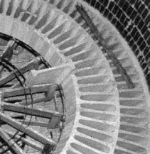
The sequence of construction for a brick arch and beam packing support is shown in the series of photos below.
The standard in self-supporting domes is the Steuler Stepped Grid Self-Supporting Dome. The dome is a result of years of research in corrosion and system engineering. The dome can be designed to span ovr 10000 mm. The dome eliminates the need for the brick arch walls which greatly reduces the weight of the entire tower. The elimination of the supporting arch walls opens up the possibility to utilizes any shape for a tower bottom the the designer wishes to employ (i.e. conical) although virtually all tower bottoms in sulphuric acid plants are either flat or dished. Domes also allow the installation of multiple packed sections in one tower without the need for additional supports. Over 285 Steuler domes have been produced. The Steuler Dome is constructed of ceramic grade SF S.
The stepped grid is now being offered by a number of different suppliers, such as Koch. Others such as Acid Piping Technology (APT) offer domes manufactured in China.
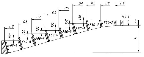
The last ring in the dome is always custom designed and produced to the suit the diameter of the vessel. A specially shapped brick at the wall supports the dome and transfers the load from the dome to the shell and down through the vessel.
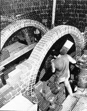
Self-supporting done under construction. A form work is used to support the dome until it is completed |
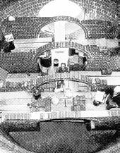
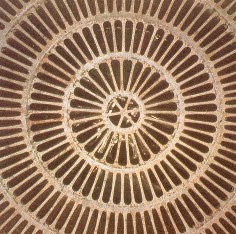
Completed dome viewed from below |
|
||||||||||||||||||||||||||||||||||||||||||||||||||
The maximum load that can be handled by the dome is dependent on the span of the dome. At a diameter of 9000 mm, the maximum load on the dome is 30 kN/m². At a diameter of 2000 mm, the dome can support three times the load (90 kN/m²).
The estimated pressure drop across a self-supporting dome is as follows:
35 Pa @ 2 m/s
25 Pa @ 1 m/s