|
||
| Sulphuric Acid on the WebTM | Technical Manual | DKL Engineering, Inc. |
Knowledge for the
Sulphuric Acid Industry
![]()
Sulphuric Acid on the Web
Introduction
General
Equipment Suppliers
Contractor
Instrumentation
Industry News
Maintenance
Acid
Traders
Organizations
Fabricators
Conferences
Used
Plants
Intellectual
Propoerty
Acid
Plant Database
Market
Information
Library
Technical Manual
Introduction
General
Definitions
Instrumentation
Plant Safety
Metallurgial
Processes
Metallurgical
Sulphur Burning
Acid Regeneration
Lead Chamber
Technology
Gas Cleaning
Contact
Strong Acid
Acid Storage
Loading/Unloading
Transportation
Sulphur
Systems
Liquid SO2
Boiler Feed Water
Steam Systems
Cooling Water
Effluent Treatment
Utilities
Construction
Maintenance
Inspection
Analytical Procedures
Materials of Construction
Corrosion
Properties
Vendor Data
DKL Engineering, Inc.
Handbook of Sulphuric Acid Manufacturing
Order
Form
Preface
Contents
Feedback
Sulphuric Acid
Decolourization
Order Form
Preface
Table of Contents
Process Engineering Data Sheets - PEDS
Order
Form
Table of Contents
Introduction
Bibliography of Sulphuric Acid Technology
Order Form
Preface
Contents


Strong Acid System - Towers -
Pressure Grouting
May 25, 2013
|
Introduction Pressure Grouting Equipment and Supplies Procedure |
Associated Links |
 The
lining of a carbon steel tower typically consists of a asphaltic mastic
(i.e.Pecora mastic) membrane followed by a sheet membrane (i.e. Rhepanol, PTFE)
and then one or more layers of acid resistant brick (i.e. red shale, fire clay).
The asphaltic mastic provides minimal protection of the carbon steel against
acid attack. The mastic is often only used to adhere the sheet membrane to
the shell. It is the sheet membrane that actually prevents the acid
from penetrating to the shell. The asphaltic mastic and sheet membrane
must be protected from the high operating and upsets temperatures that existing
in the some towers. The acid resistant brick lining provides insulation,
mechanical protection and creates a stagnation condition for any chemicals that
penetrate the brick and masonry, thus protecting the membrane. However,
the brick lining is not truly acid resistant since acid will eventually permeate
through the brick lining and come in contact with the membrane.
Installed and maintained properly, this acid resistant lining will last the life
of the plant.
The
lining of a carbon steel tower typically consists of a asphaltic mastic
(i.e.Pecora mastic) membrane followed by a sheet membrane (i.e. Rhepanol, PTFE)
and then one or more layers of acid resistant brick (i.e. red shale, fire clay).
The asphaltic mastic provides minimal protection of the carbon steel against
acid attack. The mastic is often only used to adhere the sheet membrane to
the shell. It is the sheet membrane that actually prevents the acid
from penetrating to the shell. The asphaltic mastic and sheet membrane
must be protected from the high operating and upsets temperatures that existing
in the some towers. The acid resistant brick lining provides insulation,
mechanical protection and creates a stagnation condition for any chemicals that
penetrate the brick and masonry, thus protecting the membrane. However,
the brick lining is not truly acid resistant since acid will eventually permeate
through the brick lining and come in contact with the membrane.
Installed and maintained properly, this acid resistant lining will last the life
of the plant.
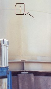
Leaks in brick lined equipment will occur when the lining is compromised and acid is allowed to come in contact with the inner membrane. This may be the result of cracks developing in the the brick or mortar. When the acid eventually reached the carbon steel shell, it will attack the carbon steel and small pinhole leaks will develop.
The proper method of repairing any leak in a lined vessel is to perform the repairs from the inside. The lining is removed until the damaged area on the shell is exposed. The shell is then repaired and the lining reinstalled. The alternative is to execute a repair from the outside of the vessel. This approach is desirable if a shutdown cannot be taken to perform a proper repair. One method commonly used in acid plants is pressure grouting.
This approach to performing a temporary repair to a leaking tower or pump tank is to fill the space between the carbon steel shell and brick lining with a material that is acid resistant, preventing further penetration of the acid to the shell. The material most commonly used for this type of repair is a two-component, halogen-free chemically setting potassium silicate mortar. This mortar is the same mortar that is used to originally install the acid resistant brick lining.
The grouting mixture must have the correct consistency in order to be pumpable. Thus the mortar must have more of a soupy, watery mixture rather than the creamy buttery consistency used when installing brick linings. As well, the grouting mixture must be capable of setting or hardening once injected into the tower.
The formulation for a pressure injection grout mixture are significantly different from that used for a brick mortar. A mixture ratio of 1.75 parts powder (by weight) to 1 part solution (by weight) is generally used for grouting rather than the 2.5:1 ratio used for mortars. The 1.75:1 may vary a little but it is important to get as much powder into the mix and still have a mixture that is pumpable. The more powder in the mix, the faster the initial set and curing of the installed grout.
The following equipment and supplies are required to perform the repair:
An alternative to a grout pump is a small pressure vessel that can be filled with grout and air pressure can be applied to it to 'pump' the grout out.
The following procedure is general in nature and should be modified to suit the particulars of the repair.
1. Clean the area around the leak of any sulphate and paint.
2. Weld threaded nipples (1/2" NPT) onto the shell in the area of the leak. The number and location of these nipples will depend on the nature and extent of the leak.
Normally, welding on any lined vessel is prohibited since damage will result to the lining due to the high temperatures generated during the welding process. In this situation, it is not a problem since the area will be subsequently repaired by grouting.
3. If the leak is more extensive a patch may need to be installed over the affected area. The threaded nipples should be attached to the patch.
4. In some cases a portion of the shell must be removed and a new section butt welded to replace the damaged section.
5. Drill a hole through the center of the threaded nipple(s).
6. Connect a "T" connection to the nipple. On one branch of the "T" connect a pressure gauge. The other branch of the "T" will be used to connect the grout pump. Use flexible high pressure hose to connect the grout 'pump' to the "T".
7. If access is available to the interior of the vessel look for crack in the brick or mortar in the vicinity of the leak. If these cracks are not sealed the grout will simply flow freely out of the crack without completely filling the voids behind the brick. Use wood wedges or similar material to seal the cracks.
7. Prepare the grout mixture to the required consistency.
8. Starting at the lowest threaded nipple, inject the grout into the vessel. Continue injecting the grout until the back pressure on the pump reaches approximately 80 psi, or grout begins coming out of the next higher nipple. If access is available to the inside of the vessel, watch for grout exiting from any crack in the brick or mortar.
9. Disconnect the grout 'pump' and plug the nipple.
10. Repeat the procedure with the next highest nipple working your way to the highest point.