|
||
| Sulphuric Acid on the WebTM | Technical Manual | DKL Engineering, Inc. |
Knowledge for the
Sulphuric Acid Industry
![]()
Sulphuric Acid on the Web
Introduction
General
Equipment Suppliers
Contractor
Instrumentation
Industry News
Maintenance
Acid
Traders
Organizations
Fabricators
Conferences
Used
Plants
Intellectual
Propoerty
Acid
Plant Database
Market
Information
Library
Technical Manual
Introduction
General
Definitions
Instrumentation
Plant Safety
Metallurgial
Processes
Metallurgical
Sulphur Burning
Acid Regeneration
Lead Chamber
Technology
Gas Cleaning
Contact
Strong Acid
Acid Storage
Loading/Unloading
Transportation
Sulphur
Systems
Liquid SO2
Boiler Feed Water
Steam Systems
Cooling Water
Effluent Treatment
Utilities
Construction
Maintenance
Inspection
Analytical Procedures
Materials of Construction
Corrosion
Properties
Vendor Data
DKL Engineering, Inc.
Handbook of Sulphuric Acid Manufacturing
Order
Form
Preface
Contents
Feedback
Sulphuric Acid
Decolourization
Order Form
Preface
Table of Contents
Process Engineering Data Sheets - PEDS
Order
Form
Table of Contents
Introduction
Bibliography of Sulphuric Acid Technology
Order Form
Preface
Contents


Contact Section - Preheat Systems
September 6, 2004
The most critical stage in the manufacture of sulphuric acid is the oxidation of
sulphur dioxide (SO2) to to sulphur trioxide (SO3) using
vanadium pentoxide catalyst. In
order for the reaction to proceed, the catalyst must be heated up to its
ignition temperature, typically 400 to 420oC prior to introducing the
sulphur dioxide containing gas. The
heating of the catalyst beds as well as other items of equipment, prior to
startup is achieved using a preheat system. 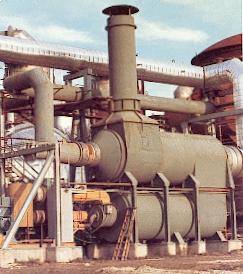
In sulphur burning plants a supplementary fuel may be burnt in the sulphur
furnace for refractory brick curing and preheating the contact section of the
acid plant.
In metallurgical acid plants a separate furnace and heat exchange system burning
a supplementary fuel is used to preheat the acid plant.
During operation with low SO2 strength
gases, insufficient heat is produced or recovered to maintain the catalyst bed
temperatures. In this situation,
the preheat system is operated to provide the additional heat.
In acid regeneration plants a combination of both systems are used to preheat
the plant. The regeneration furnace
is preheated using a supplementary fuel for refractory brick curing and
preheating. A separate furnace and
heat exchange system is used to preheat the acid plant contact system as well as
preheating combustion air for the regeneration furnace during normal operation.
The preheat system consists of a furnace, heat exchanger, combustion air and
tempering air fan and stack.
Natural gas or fuel oil is typically burned in the furnace and tempering air or
recycle gas is added to cool the combustion gases to a suitable temperature
before entering the heat exchanger. Heat
is exchanged between the combustion gas and process gas before being discharged
from a local stack.
Preheat systems are used for startup and on-line
applications. Startup preheaters
provide necessary heat to raise the catalyst bed to its ignition temperature and
heat other equipment prior to introduction of SO2 gas and as such do
not operate continuously. On-line
preheat systems are operated continuously during low SO2 strengths to
maintain the catalyst beds at ignition temperature.
On-line systems are commonly used in metallurgical and acid regeneration plants.
Three systems, illustrated in Figure 1.1 are
presented here in order of increasing overall thermal efficiency.
The choice of system is dependent on the overall thermal efficiency required by
the client.
The fuel is burned with combustion air and the combustion gases are cooled using tempering air. The combustion and tempering air enter the furnace essentially at ambient temperature. The hot combustion gases are cooled in the preheat exchanger before being discharged to atmosphere. The overall thermal efficiency is typically 50 to 60%.
The fuel is burned with combustion air and the combustion gases are cooled using a portion of the cooled gases leaving the heat exchanger instead of tempering air. This reduces the total amount of air required. The total flow to the stack is reduced due to elimination of tempering air. The overall thermal efficiency is higher than the standard system since heat is not wasted by heating the tempering air which goes up the stack. The overall thermal efficiency is typically 72 to 80%.
Recycle and Preheat Air System
Having previously reduced the combustion air to its minimum value and using the maximum amount of recycle possible, only by recovering the heat in the stack gases can the overall thermal efficiency be increased. A portion of the stack gas heat can be recovered by heating up the combustion air. As the overall thermal efficiency increases the size of the air preheater increases, thus good judgement must be used to put an upper limit on the efficiency. For any specific efficiency, the amount of heat recovered in the air preheated can be varied so that the best size combination for the air preheat exchanger and process gas heat exchanger can be achieved. The overall thermal efficiency is typically greater than 80%.
The type of fuel burned is generally specified by the client.
Generally there is a primary fuel which is used most of the time and a secondary
fuel which is used when the primary fuel is not available.
Materials must be specified to accommodate the burning of either fuel. Occasionally a third fuel such as propane is specified for
the pilot.
Gas and Light Fuel Oils versus Heavy Fuel Oils
The design of the preheat furnace and exchanger will differ depending on the
type of fuel used. Table 4.2
compares the difference in designs.
| Gas and Light Fuel Oils |
Heavy Fuel Oils |
|
| Combustion Chamber | Combustion takes place in refractory lined chamber | Combustion takes place in refractory lined chamber |
| Furnace Mixing Chamber | Ceramic fibre blanket lined. Since the fuel is relatively clean burning there is no problem with the lining absorbing the fuel. | Refractory lined. Heavy fuel oils are difficult to burn so refractory is used to ensure fuel cannot be absorbed into the lining. |
| Preheat Exchanger | Combustion gases enter on shell side since fouling is not a problem. Gas is vertically up the shell. | Combustion gases enter on tube side since the fouling problem requires the ability to clean the tubes. Gas flow is downwards or horizontal to allow draining of the tubes. |
| Inlet Vestibule | Carbon steel/ceramic fibre lined shell. The base is generally refractory lined to allow access without damaging the liner. | Carbon steel/refractory lined. |
 Preheater
furnace lined with high temperature ceramic fibre insulation in stack bond
construction which is held in place with stainless steel anchors. The
interior surfaces of the fibre insulation is sealed and protected with a thin
layer of insulating rigidizer such as Unifrax Top Coat "M" or equal. Thi
stype of lining is most suitable for gas and light fuel oils. For heavy
fuel oils a refractory bricklined is most suitable since the fuel oil will not
be absorbed into the lining material.
Preheater
furnace lined with high temperature ceramic fibre insulation in stack bond
construction which is held in place with stainless steel anchors. The
interior surfaces of the fibre insulation is sealed and protected with a thin
layer of insulating rigidizer such as Unifrax Top Coat "M" or equal. Thi
stype of lining is most suitable for gas and light fuel oils. For heavy
fuel oils a refractory bricklined is most suitable since the fuel oil will not
be absorbed into the lining material.
Assuming that the combustion reaction occurs with no heat interchange between
the furnace and its surroundings, then the total heat content of the entering
fuel and air plus the heat of combustion is available to raise the temperature
of the product of combustion. This
relationship is represented by the following heat balance:
HProducts = HReactants + HCombustion
Complete combustion of the fuel is assumed. This is the highest temperature which can be expected from the combustion process and aids in the selection of materials for the furnace.
The acid dewpoint temperature is important for the design of the preheat system
to minimize corrosion and extend the life of the furnace and preheat exchanger.
Several methods are available for calculating the acid dew point temperature. The methods will generally give a dew point temperature within 20oC of each other. The most conservative temperature should be used for the design.
|
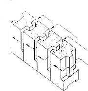
One type of furnace available is designed such that tempering air or recycle
gas supplied to the furnace plenum at the burner end of the furnace, is
circulated through the annular space between the suspended refractory wall
and the steel shell. Thus the
refractory and the shell are continually cooled.
This type of design ensures long refractory life, minimizes heat
losses and results in a cool running furnace.
Tempering air or recycle gas is introduced into the combustion chamber
through specially designed air-inlet slots in the refractory wall. This results in uniform mixing of the air with combustion gases
within the furnace and eliminates the possibility of hot spots. |
  |
The combustion equipment for a preheater consists of the following components:
There are a number of burner manufacturers supply burners for a wide range of fuels and ratings. A standard 'off-the-shelf' burner meeting the required rating is generally specified since no special features are required for an acid plant preheater. The burner will generally be equipped with a spark ignited propane/LPG/natural gas pilot assembly. For liquid fuels a supply of high pressure air is generally required for atomizing the fuel. A wide range of burners can be obtained from suppliers such as Bloom Engineering and Hauck Manufacturing.
The valve train provides for the isolation and control of the flow of fuel. The valve train generally consists of a skid mounted assembly of piping, fittings, shut-off valves, control valves and instrumentation.
If a liquid fuel is specified, an oil pump set is generally required to deliver the fuel oil to the burner at the required pressure. The oil pump skid will consist of skid mounted oil pumps (generally gear type positive displacement), filters and valving.
Fans are required to deliver combustion and dilution air to the burner and furnace. In some designs combustion and dilution air requirements are supplied by the same fan.
A package of instrumentation and controls are supplied with the preheater to control the operation of the burner. Instrumentation consists of temperature measurement, pressure switches, flow switches, UV flame detector, control valves, etc. Controls are required to regulate fuel and air flow, provide shutdown logic, control startup and shutdown sequences, and to generally monitor and maintain safe combustion. Early control systems were hardwired with relays and timers providing the control logic. Modern control systems are now micro processor based.
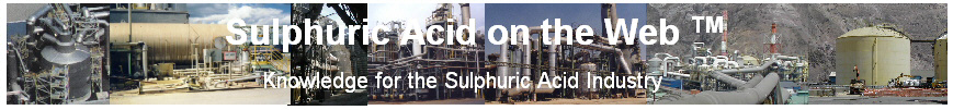
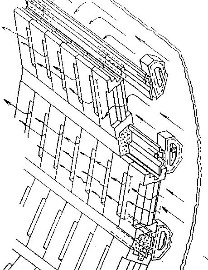
The preheat exchanger is simply a gas-to-gas heat exchanger with combustion
gases on one side and either air or process gas on the other side. There
are many different types of preheat exchangers depending on the vendor.
The normal shell and tube designs are most common with a few plate type heat
exchangers and units with finned tube bundles.
If condensation of the combustion products could occur, it is recommended to place the hot furnace gases on the tubeside of a horizontal unit. This ensures that condensed liquids will be forced out into the outlet vestibule. As well, it is easier to clean the tube side of the exchanger. When condensation is not a problem, the hot furnace gases are placed on the shellside. Combustion gases that tend to foul heat exchanger surfaces should be directed on the tube side for ease of cleaning.
The heat exchanger is manufactured in either stainless steel or carbon steel
depending on the design temperatures. The heat exchanger may be
either horizontal or vertical.
Depending on the preheat system chosen, the stack for the system may be attached
to the heat exchanger or self-supporting.
The photo shows the shell side of a horizontal preheat exchanger that will be mounted piggy-back on top of the preheat furnace. This design uses thermal insulation on the inside of the shell.
Furnace Gas Temperature to Heat Exchanger
The maximum inlet temperature of the furnace gases to the heat exchanger is
limited by the mechanical design of the exchanger.
The maximum temperature is independent of the type of fuel burned.
For all designs using stainless steel preheat exchangers the design temperature
is 750oC. The preheat
exchanger should be designed for a maximum temperature of 800oC at
which point an interlock will shutdown the preheat system.
For designs using carbon steel preheat exchangers the design temperature is 550oC.
The overall thermal efficiency is defined as follows:
% Overall
Heat removed in preheat exchanger
Thermal =
------------------------------------------------------
Efficiency
Heat input to the furnace by the fuel
This value may be specified by the client.
The initial capital cost of the preheat system usually increase with overall
thermal efficiency.
For preheat systems used in startup applications, the main concern is to keep
the initial capital cost low. By
definition, the operating costs are low since the preheat system is not operated
continuously. The standard type of
preheat system, with an overall thermal efficiency of 50-60% is commonly used
for this application.
For on-line application, operating costs should be minimized since the preheat
system operates frequently or continuously.
This can be achieved by increasing the overall thermal efficiency of the
standard preheat system by recycling the furnace gases and preheating the
combustion air. An overall thermal
efficiency greater than 72% can be achieved in this manner.
When the preheat system is used to preheat process gas containing SO2, condensation may occur resulting in corrosion of the heat exchanger. To minimize condensation, the tubewall temperature should be maintained above 180 to 200oC.
As the temperature approach at either end of the heat exchanger is reduced, the
log mean temperature difference decreases requiring more area for the same duty
and consequently increasing the size of the heat exchanger.
To avoid excessively large exchangers the recommended minimum temperature
approach at either end of the exchanger is 15oC.
The minimum amount of combustion air recommended for burning natural gas is
twenty percent above the stoichiometric amount.
Variable firing rates are required to enable operation of the preheater over a
wide range of plant operating conditions from plant heat up to supplementary
heating during low gas strengths.
The turndown that can be achieved will be dependent on the type of burner used
and the type of fuel burned. For
natural gas and light fuel oils a turndown of 8:1 should be specified.
For heavy fuel oils a turndown of 6:1 is typical.