|
||
| Sulphuric Acid on the WebTM | Technical Manual | DKL Engineering, Inc. |
Knowledge for the
Sulphuric Acid Industry
![]()
Sulphuric Acid on the Web
Introduction
General
Equipment Suppliers
Contractor
Instrumentation
Industry News
Maintenance
Acid
Traders
Organizations
Fabricators
Conferences
Used
Plants
Intellectual
Propoerty
Acid
Plant Database
Market
Information
Library
Technical Manual
Introduction
General
Definitions
Instrumentation
Plant Safety
Metallurgial
Processes
Metallurgical
Sulphur Burning
Acid Regeneration
Lead Chamber
Technology
Gas Cleaning
Contact
Strong Acid
Acid Storage
Loading/Unloading
Transportation
Sulphur
Systems
Liquid SO2
Boiler Feed Water
Steam Systems
Cooling Water
Effluent Treatment
Utilities
Construction
Maintenance
Inspection
Analytical Procedures
Materials of Construction
Corrosion
Properties
Vendor Data
DKL Engineering, Inc.
Handbook of Sulphuric Acid Manufacturing
Order
Form
Preface
Contents
Feedback
Sulphuric Acid
Decolourization
Order Form
Preface
Table of Contents
Process Engineering Data Sheets - PEDS
Order
Form
Table of Contents
Introduction
Bibliography of Sulphuric Acid Technology
Order Form
Preface
Contents

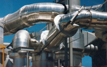
Contact Section - Gas Ducting
May 22, 2010
The gas ducting in an acid plant can be classified into three categories:
Each type of ducting has its own unique design and operating conditions.
The ducting that conveys gas from metallurgical operation must be design for hot gas (+250°C, 482°F) containing dust, metallic fumes, sulphur trioxide, etc. Dust in the gas will tend to settle in the duct even if gas velocities are kept high. The duct generally operates at or just below atmospheric pressure. The material of construction is carbon steel. The ducting will be insulated to prevent heat loss. Cooling of the gas should be avoided to prevent condensation of acid in the carbon steel ducting which will lead corrosion and gas leaks.
The ducting in the gas cleaning system of a metallurgical or acid regeneration plant must be design for a wet corrosive environment. The maximum operating temperature is generally below 80°C (176°F). The operating pressure is generally less than atmospheric with the maximum vacuum occurring at the inlet of the drying tower just ahead of the acid plant blower. The material of construction is fibreglass reinforced plastic (FRP) or dual laminate. FRP ducting is rarely insulated since there is no requirement to retain heat and temperatures are low enough so insulation is not required for personnel protection.
The ducting in the contact section of an acid plant handles gas from ambient temperatures up to 630°C (1166°F). The materials of construction are generally carbon steel for ducting operating under 450°C (842°F) and metallized carbon steel or stainless steel for higher temperatures. Stainless steel (316L SS) may be used at lower temperatures instead of carbon steel since it has more resistance to corrosion. Ducting will be insulated to minimize heat loss and for personnel protection.
Ducting at the outlet of sulphur and acid regeneration furnace are special cases since they operate at much higher temperatures than normal ducting. The ducting must be refractory lined to properly convey the hot gas. Ducting between equipment is generally short kept short for this reason.
Special attention is required for ducting at the inlet to the gas cleaning system where hot gas enters the quench system. In this area, ducting is exposed to hot gases, humid conditions, wet/dry conditions, etc. The extremely aggressive and variable conditions requires the used of either specialty alloys or acid resistant brick lining.
The size of a gas duct is directly related to the volumetric flow rate of gas through the duct. Ducting that is too small will have an excessively high pressure drop which could impact the gas handling capacity of the plant. The high velocity may adversely affect gas distribution as the gas enters a vessel such as a tower or converter. Velocity on its own cannot be used as a sizing criteria since a high velocity (i.e. 30 m/s, 98 ft/s) in a large duct has a lower specific pressure drop (i.e. mm WC/100 m) than the same velocity gas through a smaller duct.
| Gas Flow | DP100 | Diameter | Velocity |
| 84950 Nm³/h | 19.2 mmWC/100 m | 1295 mm | 17.9 m/s |
| 50000 SCFM | 0.23 in. WC/100 ft | 51 inches | 58.78 ft/s |
| 169901 Nm³/h | 19.2 mmWC/100 m |
1676 mm |
21.4 m/s |
| 100000 SCFM | 0.23 in. WC/100 ft | 66 inches | 70.19 ft/s |
In a typical plant, the ducting pressure losses will constitute approximately 10% of the total plant pressure drop excluding inlet/outlet losses at equipment nozzles. In a conservatively design plant the proportion may be only 8% of the total plant pressure drop. If the capacity of a plant has been expanded without changing the duct sizes, this proportion may be as high as 15%.
Sizing criteria for ducting varies from one plant designer to another. A DP100 criteria is generally the basis for ducting sizing whether it is calculated for each duct or whether it is pre-calculated for a range of flows and presented in a selection table.
The primary purpose of gas ducting is to convey gas from one piece of equipment to another. To perform this function properly, careful design of the ducting is required to accommodate the operating temperature and pressure and the stresses and forces created by thermal expansion of the ducting and the equipment it connects.
The layout of the plant determines the ducting arrangement for the plant. A compact plant layout results in the shortest duct runs but the plant ends up quite congested. Ducting cost is minimized but the design of the ducting is more difficult since expansion and movement must be absorbed in a shorter length.
Expanding the location of equipment allows more flexibility in terms of ducting runs. Expansion and movement of ducting is more easily absorbed in longer duct runs. Access to equipment is also easier but ducting costs increase.
The operating conditions inside the duct is a factor that is considered when design a duct. The operating temperature is the primary factor since it affects the strength of the duct material and is directly related to the amount of thermal expansion. Operating pressures are low and does not significantly affect the wall thickness calculations.
The high operating temperatures in the contact section of an acid plant results in large thermal expansions in the equipment and ducting. If the thermal expansion is not adequately accounted for in the design the result will be equipment and ducting failures leading to gas leaks. In the case of ducting, thermal expansion is allowed for by installing expansion joints in the ducting.
Expansion joints are designed to accommodate basically three types of movements: axial, lateral and angular.
| Axial - Displacement in the same direction as the axis of the duct. The expansion joint responds by compressing or expanding along its axis. | 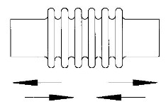 |
| Lateral - An offset of the axis of the duct where the movement is in the same plane. This type of displacement will occur when two vessels joined by a straight piece of duct expand different amounts due to temperature changes. | 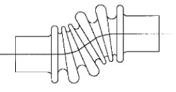 |
| Angular - Bending of the duct. | 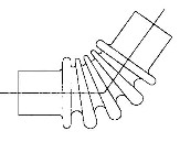 |
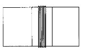
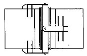
Expansion joints come in various forms, each designed to accommodate one or more of the three movements. There are basically two types of expansion joints used in hot metallic gas ducting; single or multiple convolution expansion joints. The single convolution expansion joints are sometimes referred to as ‘donut’ expansion joints.
| Single
Convolution ‘Donut’ |
Multi-Convolution |
|
| Wall Thickness |
6 mm (0.25”) |
1.5 mm (0.06”) |
| Height of Convolution | 300 to 600 mm (12”
to 24”) |
50 to 100 mm (2” to
4”) |
| Width |
100 to 150 mm (4”
to 6”) |
150 to 500 mm (6”
to 20”) |
| Flexibility |
Low |
High |
| Movement |
Axial only |
Single: Axial and
Angular |
| Double: Lateral |
||
| Transmitted Loads |
High |
Low |
| Material of Construction |
CS or SS - Same as
duct material |
SS |
| Cost |
Low |
High |
| Maintenance |
Can be repaired by
welding |
Material is too
thin to be easily repaired |
| Support |
Fewer duct supports
are required due to the stiffness of the joint |
High flexibility of
joint requires more duct supports. |
Types of Expansion Joints
| Single - A single expansion joint consisting of multiple convolutions. A single expansion joint is used when movements are small. |
|
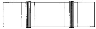
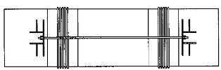
| Double - A double expansion joint consists of two expansion joints along the same straight section of duct. Using two expansion joints allows for greater movement. |
|
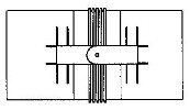
| Hinged - Used where movement is angular in nature. The hinge allows movement only in one plane. |
|
| Gimbal - Used where movement is angular in nature. The gimbal or double hinge allows more freedom of movement in multiple planes. |
|
| Tied - Expansion joints are tied so that the forces in the ducting are not carried by the expansion joints which can be easily damaged. |
|
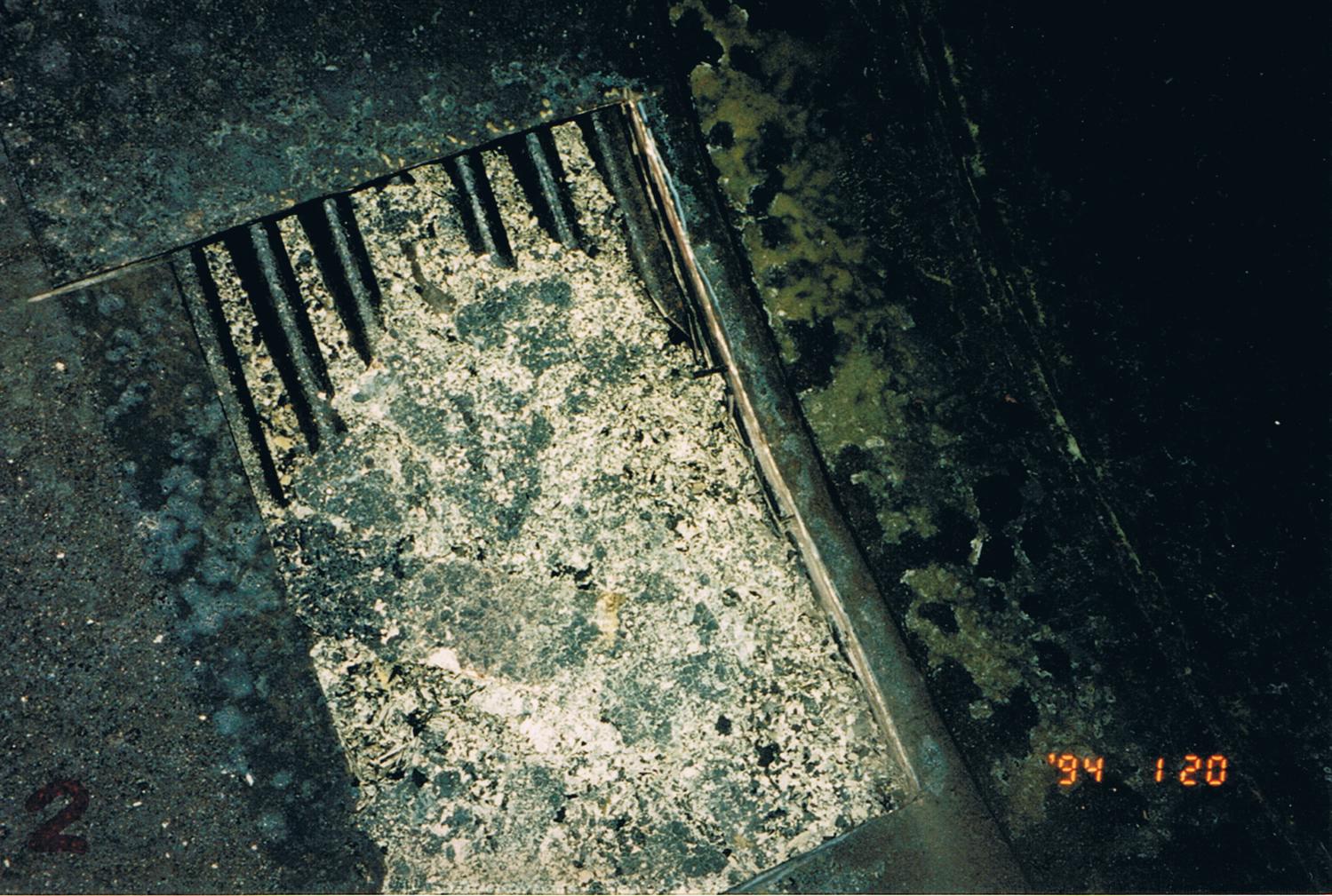
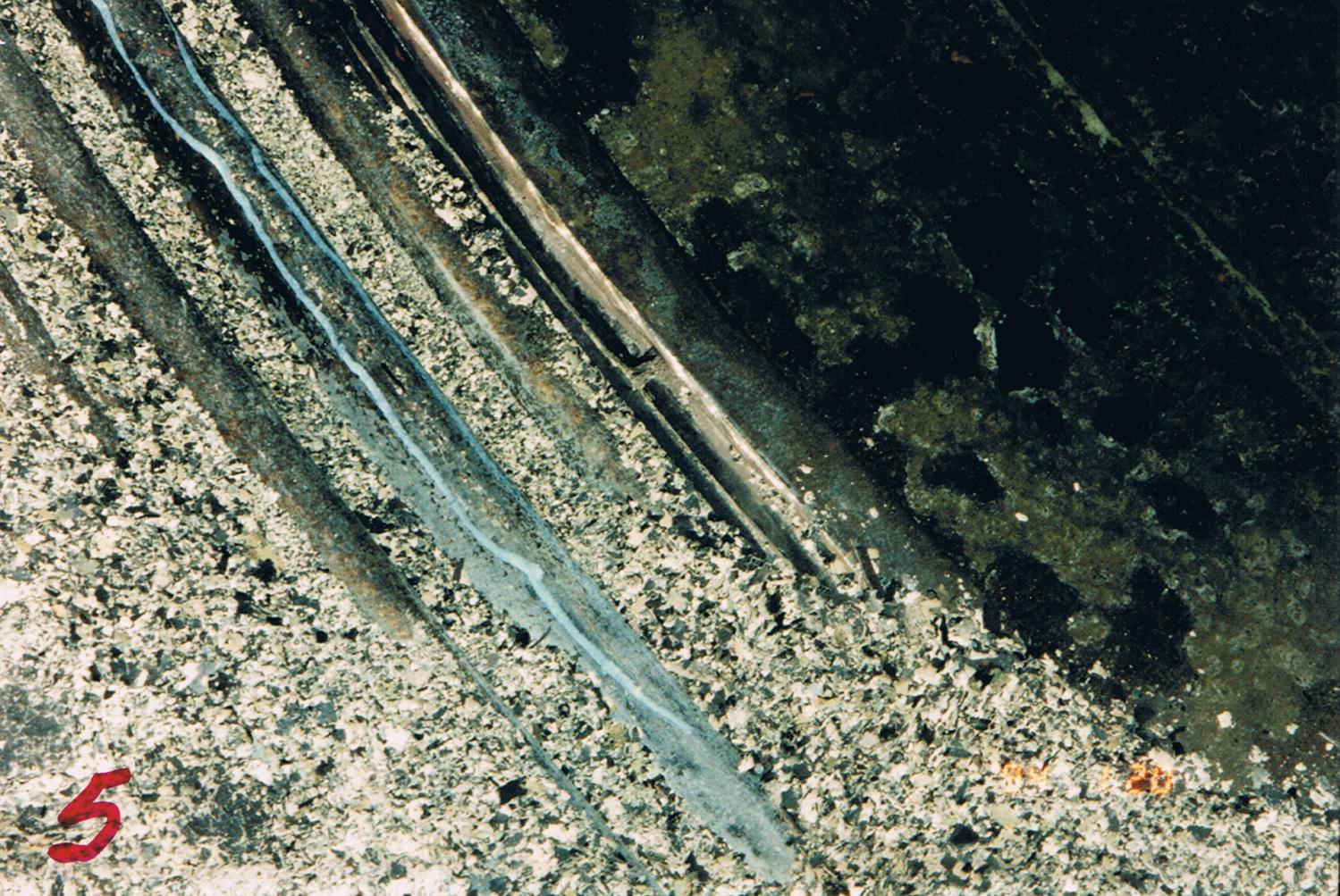
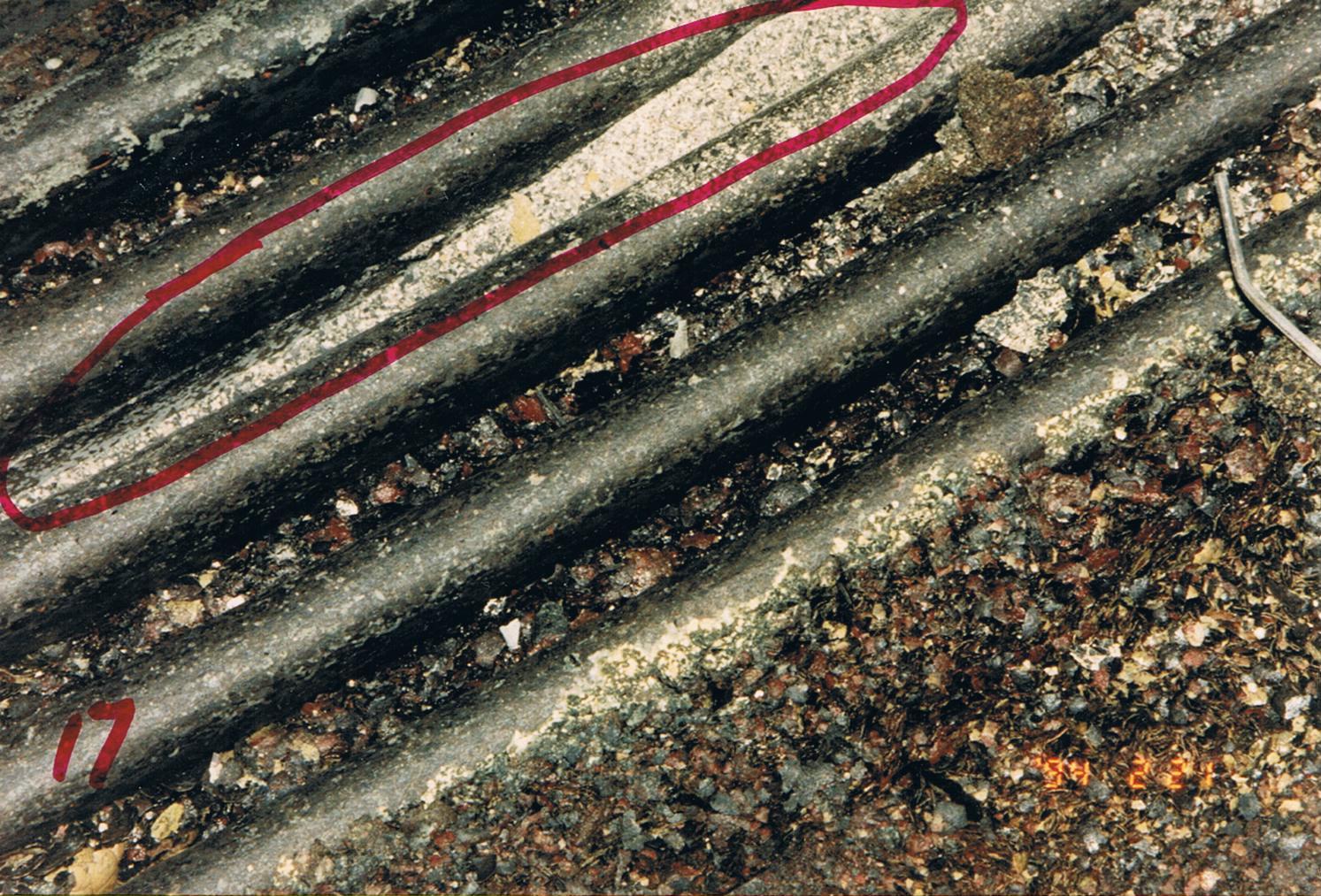
One problem commonly experienced with expansion joints is the accumulation of sulphate inside the convolutions. The sulphate packs in very tightly restricting the movement of the joint. As well, corrosion of the thin wall expansion joint is accelerated which leads to eventual gas leaks. The photo to the right shows an expansion joint with the expansion joint liner plate removed. Sulphate can still accumulate inside even though the cover plate is present to minimize the ingress of material into the expansion joint. This particular expansion joint has corroded and cracked so that gas was leaking from the expansion joint.