|
||
| Sulphuric Acid on the WebTM | Technical Manual | DKL Engineering, Inc. |
Knowledge for the
Sulphuric Acid Industry
![]()
Sulphuric Acid on the Web
Introduction
General
Equipment Suppliers
Contractor
Instrumentation
Industry News
Maintenance
Acid
Traders
Organizations
Fabricators
Conferences
Used
Plants
Intellectual
Propoerty
Acid
Plant Database
Market
Information
Library
Technical Manual
Introduction
General
Definitions
Instrumentation
Plant Safety
Metallurgial
Processes
Metallurgical
Sulphur Burning
Acid Regeneration
Lead Chamber
Technology
Gas Cleaning
Contact
Strong Acid
Acid Storage
Loading/Unloading
Transportation
Sulphur
Systems
Liquid SO2
Boiler Feed Water
Steam Systems
Cooling Water
Effluent Treatment
Utilities
Construction
Maintenance
Inspection
Analytical Procedures
Materials of Construction
Corrosion
Properties
Vendor Data
DKL Engineering, Inc.
Handbook of Sulphuric Acid Manufacturing
Order
Form
Preface
Contents
Feedback
Sulphuric Acid
Decolourization
Order Form
Preface
Table of Contents
Process Engineering Data Sheets - PEDS
Order
Form
Table of Contents
Introduction
Bibliography of Sulphuric Acid Technology
Order Form
Preface
Contents

Maintenance and Inspection - Preheat
System
September 6, 2004
|
Introduction Problems |
Associated Links |
The manufacturer’s maintenance procedures and recommendations should be reviewed and strictly adhered to in order to ensure the proper operation of the equipment. The following is provided as a general guideline only.
| Preheat
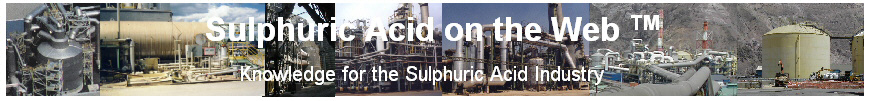
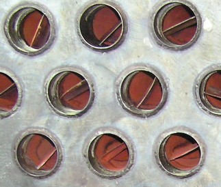
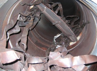
Exchanger Inserts To enhance heat transfer on the tube side of the heat exchanger, some manufacturers use inserts in the tubes. The inserts are thin gauge metal strips that have been twisted and inserted into the tubes. The twist in the metal strip will cause the gas to swirl down the tubes increasing turbulence near the tube wall and increasing the heat transfer coefficient. This allows the exchanger size to be reduced with a corresponding reduction in cost. In one design, the metal strips are inserted into the tubes loose and secured at the inlet end by a single weld. The outlet end is left loose so that the metal strip is free to move and expand. In one heat exchanger, the weld holding the metal strip in place broke allowing the inserts to be blown out of the tube and into the outlet duct from the heat exchanger. The inserts eventually got caught in a downstream damper causing it to eventually fail as the actuator was trying to close the damper fully but was not able to due to the large number of inserts that had wedged themselves in and around the damper. The mode of failure appeared to be a broken weld caused by excessive vibration of the metal strip which weakened the weld. The problem was eventually discovered during a shutdown and when an investigation was done to see why the damper was not closing fully. The missing inserts were replaced and to ensure that the inserts would not break free again a second weld was placed on the metal strip at the inlet end of the exchanger. This would hopefully prevent the leading edge of the insert from vibrating at the tube inlet. As well, a screen was place at the outlet of the exchanger to catch any inserts should they break away. |
|