|
||
| Sulphuric Acid on the WebTM | Technical Manual | DKL Engineering, Inc. |
Knowledge for the
Sulphuric Acid Industry
![]()
Sulphuric Acid on the Web
Introduction
General
Equipment Suppliers
Contractor
Instrumentation
Industry News
Maintenance
Acid
Traders
Organizations
Fabricators
Conferences
Used
Plants
Intellectual
Propoerty
Acid
Plant Database
Market
Information
Library
Technical Manual
Introduction
General
Definitions
Instrumentation
Plant Safety
Metallurgial
Processes
Metallurgical
Sulphur Burning
Acid Regeneration
Lead Chamber
Technology
Gas Cleaning
Contact
Strong Acid
Acid Storage
Loading/Unloading
Transportation
Sulphur
Systems
Liquid SO2
Boiler Feed Water
Steam Systems
Cooling Water
Effluent Treatment
Utilities
Construction
Maintenance
Inspection
Analytical Procedures
Materials of Construction
Corrosion
Properties
Vendor Data
DKL Engineering, Inc.
Handbook of Sulphuric Acid Manufacturing
Order
Form
Preface
Contents
Feedback
Sulphuric Acid
Decolourization
Order Form
Preface
Table of Contents
Process Engineering Data Sheets - PEDS
Order
Form
Table of Contents
Introduction
Bibliography of Sulphuric Acid Technology
Order Form
Preface
Contents

Contact Section - Gas-to-Gas Heat
Exchangers
February 25, 2011
Within the contact section of an acid plant heat is generated from the exothermic reaction of SO2 to SO3. The multi-stage nature of the process requires that this heat is removed from the process gas in order to obtain the highest possible conversion efficiency. In a sulphur burning acid plant much of this excess heat is used to generate high pressure steam. Some of the heat is also used to reheat the process gases, such the gas returning from the intermediate absorption system. In a metallurgical acid plant most of the heat is use to reheat either the cold gas coming from the gas cleaning system or reheating the gas from the intermediate absorption system.
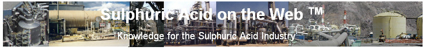
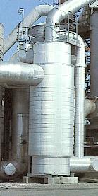
The transfer of heat from one process gas to another gas is done in a gas-to-gas heat exchanger, so called because gas is flowing on both the shell and tube side of the heat exchanger. A gas-to-gas heat exchanger usually takes the form of a vertical shell and tube heat exchanger. Variations of the standard design are horizontal units, plate type heat exchangers and heat exchangers that are located inside the converter vessel.
'Conventional' Gas-to-Gas Heat Exchangers
The conventional gas-to-gas heat exchanger is vertical shell and tube heat exchanger with single segmental baffles. These exchangers are typically overdesigned for the intended duty because of the following:
In a heat exchanger with single segmental baffles, gas will flow across the tube bundle first and then parallel to the tubes before encountering the next baffle which forces the gas back across the tubes. The different flow patterns on the shell side makes it difficult to design and predict heat transfer coefficients.
The non-uniform temperature profile across the tube bundle leads to thermal stresses which can lead to tubesheet warpages and tube-to-tubesheet joint failures.
An improvement on the single segmental baffle is the double segmental baffle. The gas is introduced to the two bundle at two points 180° apart. The gas flows across the tube towards the centre of the tube bundle by two baffles. At the centre of the tube bundle the space between the baffles allows the gas to flow along tubes into the next baffle section. A single baffle located in the centre of the tube bundle forces the gas back out across the tube bundle towards the shell. This pattern of flow is repeated until the desired thermal characteristics are achieved. The advantage of the double segmental baffle is that the flow is split in two inside the tube bundle such that only half the gas flow is crossing the bundle. This means that the pressure drop will be less than the single segmental baffle arrangement, everything else being equal. However, there are still a mixture of cross and longitudinal flow within the tube bundle. Double segmental heat exchangers require large bustles to distribute the gas to points 180° apart on the shell. The flexibility of shell side nozzle placement is improved but the inlet and outlets must still be in-line with each other.
A futher improvement is the so-called no-tubes-in-window design which omits all the tubes within the baffle window. The flow of gas is now essentially always across the tube bundle which makes predicting shell side heat transfer coefficients easier. The disadvantage is that the shell of the exchanger is generally larger to accomodate all the tubes within the overlap of the baffles and to minimize overall pressure drop.
The principal behind the radial flow heat exchangers is the use of disc and dount baffles. The dount baffle forces the gas to flow from the outside to the inside and through the hole in the middle of the baffle while the disc baffle does the opposite. Placing the tubes within the overlapping area of the disc and donut baffles means the all the gas flow will be essentially across the tubes only. The disc and donut baffles are symmetrical around their centres so it does not matter where the gas enters or exits the shell side of the heat exchanger. This allows the maximum freedon to place shell side nozzles.
The symmetrical layout of the tubes means that the temperature profile across the tube sheet will also be symmetrical. The stresses occurring in the tubesheet will be more uniform and hence there will be less chance of failures of the tubesheet or tube-to-tubesheet joints.
Many different tube layouts can be used with a disc and donut baffle arrangement. The simplest is to utilize a standard 30° or 60° tube layout and remove all the tubes that fall in the baffle windows. The tube layout will not be perfectly symmetrical but with enough tube 'rows' across the flow path the unsymmetrical layout becomes less of a factor.
There are several patented tube layouts available from equipment suppliers. Kvaerner Chemetics offers a perfectly symmetrical tube layout where the tube are layout in concentric rings where the tube lies between the two closest tubes of the adjacent ring. The perfect symmetry allows heat transfer coefficients and pressure drops to be accurately predicted thus minimizing overdesign of the units due to excessive safety factors. One interesting disadvantage of the symmetrical tube layout is the generation of noise due to vortex shedding.
Another tube layout patented by CECEBE Technologies places the tubes on large radius concentric arcs. Typically, five of these concentric arcs form the overall tube layout. Where the arcs meet each other, tubes are palced to fill in the discontinuities created where the arcs meet. Thus the tube lay is not perfectly symmetrical.
Regardless of the tube pattern, it is the use of the disc and donut baffle that has optimized the design of the gas-to-gas heat exchanger.
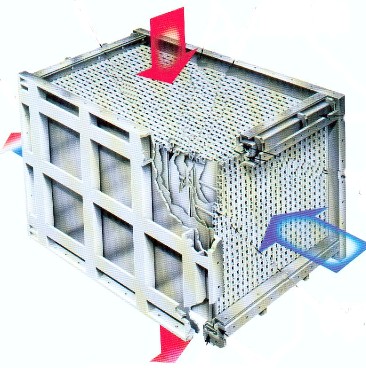
Plate type heat exchangers are relatively new to the industry. The principal of plate heat exchangers is similar to the plate heat exchangers used in acid cooling service. The cooling and heating streams flow on either side of a thin plate through which heat transfer occurs.
Enviro-Chem Systems currently are the only supplier offerring plate type heat exchangers which they refer to as MonPlex. The heat exchanger is modular in construction allowing it to be fully shop fabricated and expanded easily. Different materials of construction can be used for the modules taking advantage of better corrosion resistance or high temperature strength.
The MonPlex design uses a floating plate pack contained within a rigid housing. The design allows for thermal expansion and contraction with minimal stress on the components. The gas passages are easily accessible on both sides of the exchanger unlike a shell and tube unit where the tube side is easily inspected and cleaned while the shell side is near impossible to access.
One limitation of the MonPlex design is its in ability to handle applications where there is a significant difference in pressure between the two streams.
The improvements in the thermal design of heat exchangers is only a small part of the overall story of the improvements in gas-to-gas heat exchangers. The use of stainless steels has improved the reliability and life of the units.
The traditional material of construction is carbons steel for the tubes, tubesheets and shell of the heat exchanger. From a design temperature point of view, carbon steel is suitable for the Cold and Cold Reheat Exchangers where the operating temperatures are below 482°C (900°F). For the Hot and Hot Reheat Exchangers, where operating temperatures exceed 482°C (900°F) metallizing of the interior surface is done to prevent high temperature scaling of the carbon steel surface. Metallizing the surface does not address the problem of the reduce strength of the material at elevated temperatures. The designer of the heat exchanger must take this into account when doing the mechanical design of the unit. The tubes are also Alonized to prevent high temperature scaling of the tube surface.
An improvement to metallizing and Alonizing is the use of stainless steel for the heat exchangers where operating temperatures exceed 482°C (900°F). High temperature scaling is not a problem with stainless steel and it also retains more of its mechanical strength at the higher operating temperatures. Stainless steel may also be used in the Cold and Cold Reheat Exchangers to offset the effects of corrosion due to acid condensation at the cold end of the heat exchanger.
Hot Exchangers are generally cool the hot gases leaving the first catalyst pass before entering the second catalyst pass. The cooling medium is generally the partially heated gas entering the plant going to the first catalyst pass. Hot exchangers are exposed to the highest gas temperatures exit Bed 1 of the converter. Maximum temperatures can reach as high as 625°C depending on gas strength..
The design basis for the Hot Heat Exchanger is generally operation at the high gas strength. The reaction of SO2 to SO3 generates more heat which increases the heat load and size of the hot exchanger.
Early designs were constructed of carbon steel but problems were encountered due to high temperature oxidation and lack of mechanical strength at the high operating temperature. High temperature oxidation problems were overcome by Alonized tube and metallizing. However, the lack mechanical strength was still a problem. Some of the mechanical design problems could be overcome by having the hot gas entering the top of the exchanger and flow downwards through the tubes. This allowed the bottom of the exchanger to be designed for the lower operating temperature (410 to 430°C) rather than the +600°C inlet temperature. Designers still had acceptable mechanical stress values in which to design the lower part of the exchanger and lower tube sheet to support the weight of the tube bundle.
A novel
approach to circumvent this problem was to install the exchanger in a horizontal
position which reduced the stresses on the tube sheet.
With the introduction of stainless steels as a material of construction, high
temperature oxidation and low mechanical strength problems have been virtually
eliminated.
Condensation of acid from the gas is not a problem during normal operation so there are no restrictions on the placement of the hot gas (SO3 gas) on the shell side or tube side of the unit. The decision on which gas goes on the shell or tube side, upflow or downflow will be determined from the ducting layout, placement of converter beds or whether the exchanger is internal or external to the converter.
Hot heat exchangers are generally design with tubes conforming to ASTM A249 – Standard Specification for Welded Austenitic Steel Boiler, Superheater, Heat-Exchanger and Condenser Tubes. The material will be either Type 304 (0.040 to 0.080% C) or Type 304H (0.04% C min). Hot exchangers are not exposed to condensing conditions so thinner walled tube are used, generally 13 or 14 BWG (2.41 mm or 2.11 mm, respectively) (0.095 in or 0.083 in respectively).
Cold exchangers are generally the first heating stage for the incoming gas and the final cooling stage for the gas entering the final absorbing tower. For high gas strengths where excess heat is generated the cold exchanger maybe followed by an SO3 cooler or economizer.
The design basis for the Cold Exchanger will generally be the low gas strength operating condition or autothermal condition of the plant. At low gas strengths, the heat generated in the converter from the reaction of SO2 to SO3 is less so there is less heat available to heat the gas entering the plant to the first catalyst pass. More heat must be recovered from the hot gas to reheat the cold gas so temperature approaches are smaller resulting in a larger heat exchanger.
Cold exchangers are generally constructed of carbon steel since the operating temperatures are not as high as in hot exchangers. The problem that cold exchangers must contend with that hot exchanger do not, is the possibility of acid condensation. From a corrosion point of view, carbon steel is not the best choice of materials.
Condensation will occur when the hot SO3 bearing gases are cooled by the cold SO2 bearing gas entering the plant. The bulk gas temperature may still be above the acid dew point but the temperature of the tube wall will be below the acid dew point since the incoming cold gas temperature is generally below the acid dew point.
If there is the possibility of condensation, the process gas should enter the exchanger so that it flows down the tubes. This allows any liquid to drain out of the tubes and collect in the lower vestibule where it can be periodically drained. If the gas is allowed to flow up the tubes, the condensed liquid will tend to reflux at a certain point up the tubes and localized corrosion will occur leading to failure of the tubes and gas leaks. The tube side can also be more easily cleaned of sulphate build up than the shell side of the heat exchanger.
The gas should not be placed on the shell side since it is difficult to drain liquid than collects in the exchanger and the shell side is more difficult to clean.
If condensation cannot be avoided, the life of the unit will be short. The entire unit must be replaced or re-tubed if enough leaking tubes are plugged and the unit can no longer meet the required performance. When a unit is inspected what is often discovered is that tube failure occurs only in the region where condensation occurs and the majority of the tube is still in good condition. This localized tube failure leads to the use of a sacrificial tube bundle where the exchanger is split into two sections; a main bundle and a sacrificial bundle. When the inevitable acid condensation, tube corrosion and failure occur, the small sacrificial bundle is the only section that needs to be replaced and not the entire unit.
If the sacrificial bundle is constructed of stainless steel, it will further increase the life of the equipment and reliability of the plant.
Cold exchangers are generally constructed of carbon steel tubes conforming to ASTM A178 – Standard Specification for Electric-Resistance-Welded Carbon Steel and Carbon-Manganese Steel Boiler and Superheater Tubes or ASTM A214 – Standard Specification for Carbon Steel Heat-Exchanger and Condenser Tubes.
Since corrosion of the tubes will occur, heavier gauge tubes can be used to extend the life of the equipment. Tubes will generally be 12 BWG (2.77 mm (0.109 in)) wall thickness although 10 BWG (3.40 mm (0.134 in)) have been specified in some cases.
For superior corrosion resistance, a Cold Exchanger can be constructed of stainless steel conforming to ASTM A249 – Standard Specification for Welded Austenitic Steel Boiler, Superheater, Heat-Exchanger and Condenser Tubes. Grade 316L with a wall thickness of 14 BWG (2.11 mm (0.083 in)) is typically used.
Hot Interpass Exchangers (or Intermediate Reheat Exchangers) are generally found in double absorption plants cooling the gas exiting the second catalyst bed before its enters the third catalyst bed. The cooling medium is generally cold gas returning from the Interpass Absorbing Tower being heated to the catalyst ignition temperature.
The design basis for the Hot Interpass Exchanger is generally operation at the high gas strength. The reaction of SO2 to SO3 generates more heat which increases the heat load and size of the Hot Interpass Exchanger.
Hot Interpass Exchangers have similar duties to Hot Exchangers so the design considerations, materials of construction, tubes, etc. will also be similar. The operating temperature range is not as high as a Hot Exchanger since the temperature exit the second catalyst bed is not as high.
Cold Interpass Exchangers (or Cold Reheat Exchangers) are generally found in double absorption plants cooling the gas before it enters the Interpass Absorbing Tower. For high gas strengths where excess heat is generated the Cold Interpass Exchanger maybe followed by an SO3 cooler or economizer. The cooling medium will generally be the cold gas exiting the Interpass Absorbing Tower which must be heated back up to the catalyst ignition temperature prior to undergoing further conversion. The Cold Interpass Exchanger is the first heating step and is generally followed by the Hot Interpass Exchanger.
The design basis for the Cold Interpass Exchanger will generally be the low gas strength operating condition or autothermal condition of the plant. At low gas strengths, the heat generated in the converter from the reaction of SO2 to SO3 is less so there is less heat available to reheat the gas leaving the Interpass Absorbing Tower. More heat must be recovered from the hot gas to reheat the cold gas so temperature approaches are smaller resulting in a larger heat exchanger.
Cold Interpass Exchangers have similar design considerations, materials of construction, tubes, etc. with Cold Exchangers.
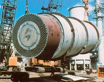
SO3 Coolers are generally required when the plant operates at high gas strengths and more heat is generated in the converter than is required to heat the cold gas(es) to the bed inlet temperatures. The excess heat shows up at the inlet of the absorber tower where the temperature becomes excessively high. High temperatures entering the absorbing towers may damage the tower brick lining and result in excessive acid mist formation amongst other operating problems.
SO3 Coolers use ambient air to remove the excess heat. The hot air produced is often simply vented to atmosphere but in some cases, the hot air can be utilized for process duties. In one case, the hot air is sent to the smelter stack to increase the buoyancy of the gas to aid in dispersion. In another case the hot air is sent to a boiler where low pressure steam is produced.
SO3 Coolers can be located in series either upstream or downstream or in parallel with a Cold or Cold Interpass Exchanger. When the SO3 Cooler is located in series, it will add to the overall plant pressure profile whereas in parallel no addition pressure drop is added to the plant. This will be a consideration in new plant designs but will be more important in plant retrofits where blower capacity may be limited.
Condensation of acid in the SO3 Cooler is more of a problem than in Cold or Cold Interpass Exchangers since ambient air (i.e. colder cooling medium) is used which results in colder tube wall temperatures.
Upstream of a Cold or Cold Interpass Exchangers
In the upstream position, the SO3 Cooler removes excess heat and lowers the temperature of the gas prior to entering either a Cold or Cold Interpass Exchanger. The lower temperature reduces the log-mean temperature difference for the Cold or Cold Interpass Exchanger and may result in an increase in the size of the exchanger depending on the exact design conditions for the exchanger.
When an SO3 Cooler is positioned upstream, condensation is not as critical since the temperature difference will be greater and the tube wall temperature will not be below the acid dew point temperature.
Downstream of a Cold or Cold Interpass Exchangers
In the downstream position, the SO3 Cooler will be subject to colder operating temperatures which will result in the possibility of acid condensation on the process gas side of the exchanger.
The Cold or Cold Interpass Exchanger design basis is not affected by the downstream SO3 Cooler.
In the parallel position, the SO3 Cooler and Cold or Cold Interpass Exchangers see similar process conditions. Since a portion of the flow goes through the SO3 Cooler, the design basis of the Cold or Cold Interpass Exchangers may be affected by the presence of the SO3 Cooler.
The design pressure drop of the plant is not affected when the SO3 Cooler is in parallel with the other exchangers. During normal operation the pressure drop will be reduced since the gas flow will more than likely be split between the two heat exchangers.
The SO3 Cooler will be subject to intermittent and varying operation since its purpose is to remove excess heat which may not always be present depending on operating conditions. When the operation of the upstream process varies considerably in both flow and SO2 concentration (i.e. copper smelter/converter), the duty on the SO3 Cooler will also vary. When gas strengths are low there may be no excess heat to be removed.
In the parallel position, all the process gas is simply put through the Cold or Cold Interpass Exchangers with no gas being diverted through the SO3 Cooler. When the SO3 Cooler is in series, the process gas must be bypassed around the exchanger or the flow of cooling air stopped completely.
The design of the SO3 Cooler must take into consideration all these variations in operation. The mechanical design of the unit must be done with care to avoid failures due to differential expansion from no flow conditions on either the process gas or cooling medium side of the exchanger.
Acid condensation is a major concern with SO3 Coolers since they operate with much colder ambient air as the cooling medium. There are several ways to address this problem in both design and operation of the equipment.
Recycling hot air from the exit of the SO3 Cooler to the inlet is the most popular way to reduce the risk of acid condensation. A duct is simply installed from the exit of the heat exchanger to the suction of the SO3 Cooler Fan. A temperature control loop is required for the inlet air temperature which controls a damper on the recycle line. A damper on the fan suction upstream of the recycle line may be required to completely cut off the supply of ambient air when there is little or no heat load on the SO3 Cooler.
The hotter cooling air increases the tube wall temperature at the process gas outlet minimizing the chance of acid condensation. Unfortunately, the higher inlet temperature reduces log-mean temperature difference resulting in a larger heat exchanger.
The varying heat load on the SO3 Cooler requires control of the cooling air flow so that the process gas is not overcooled. A temperature control loop controls the temperature of the process gas leaving the SO3 Cooler by varying the flow of air to the unit. This is accomplished by adjusting the inlet guide vanes of the SO3 Cooler Fan or adjusting the speed of the fan if it is equipped with a variable frequency drive (VFD). When there is little or no heat load on the SO3 Cooler the air flow will be at its minimum.
On-off operation of the SO3 Cooler Fan should be avoided as much as possible as this leads to thermal stresses in the heat exchanger which will eventually lead to failure of the unit.
Since there is the possibility of condensation, the process gas should enter the exchanger so that it flows down the tubes. This allows any liquid to drain out of the tubes and collect in the lower vestibule where it can be periodically drained. If the gas is allowed to flow up the tubes, the condensed liquid will tend to reflux at a certain point up the tubes and localized corrosion will occur leading to failure of the tubes and gas leaks. The tube side can also be more easily cleaned of sulphate build up than the shell side of the heat exchanger.
The gas should not be placed on the shell side since it is difficult to drain liquid than collects in the exchanger and the shell side is more difficult to clean.
The SO3 Cooler can be constructed of carbon steel since the operating temperatures are not high enough to warrant the higher strength of 304 stainless steel. However, the superior corrosion resistance of stainless steel should be considered for this duty. In this case, an exchanger constructed of 316L SS will offer the added corrosion resistance although at a much higher cost than a carbon steel unit.
Stainless steel should certainly be considered for an SO3 Cooler installed in parallel or downstream of the Cold or Cold Interpass Exchangers. In the upstream position, carbon steel is more than adequate since the possibility of acid condensation is less.