|
||
| Sulphuric Acid on the WebTM | Technical Manual | DKL Engineering, Inc. |
Knowledge for the
Sulphuric Acid Industry
![]()
Sulphuric Acid on the Web
Introduction
General
Equipment Suppliers
Contractor
Instrumentation
Industry News
Maintenance
Acid
Traders
Organizations
Fabricators
Conferences
Used
Plants
Intellectual
Propoerty
Acid
Plant Database
Market
Information
Library
Technical Manual
Introduction
General
Definitions
Instrumentation
Plant Safety
Metallurgial
Processes
Metallurgical
Sulphur Burning
Acid Regeneration
Lead Chamber
Technology
Gas Cleaning
Contact
Strong Acid
Acid Storage
Loading/Unloading
Transportation
Sulphur
Systems
Liquid SO2
Boiler Feed Water
Steam Systems
Cooling Water
Effluent Treatment
Utilities
Construction
Maintenance
Inspection
Analytical Procedures
Materials of Construction
Corrosion
Properties
Vendor Data
DKL Engineering, Inc.
Handbook of Sulphuric Acid Manufacturing
Order
Form
Preface
Contents
Feedback
Sulphuric Acid
Decolourization
Order Form
Preface
Table of Contents
Process Engineering Data Sheets - PEDS
Order
Form
Table of Contents
Introduction
Bibliography of Sulphuric Acid Technology
Order Form
Preface
Contents


Strong Acid System -
Mist Eliminators - Brownian Diffusion Candles
April 9, 2018
|
Introduction Gas Velocities Pressure Dop Candle Drains Candle Tubesheet Problems |
Associated Links |
All three-collection mechanisms are employed in Brownian diffusion candles but Brownian diffusion is the mechanism which allows these elements to achieve the high collection efficiencies.
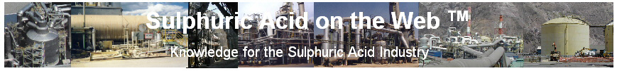
Brownian diffusion candles are made of glass fibres hand packed or wound in between two metal cages or machine wound onto the inner cage with an outer cage added on top. The candles are installed in either the hanging or standing position.
Design bed velocities are very low and range from 0.025 to 0.2 m/s (5 to 40 ft/min) depending on the pressure drop and collection efficiency desired. The absolute maximum gas velocity through the bed is 0.25 m/s (50 ft/min). In contrast to the other type of mist eliminators, the collection efficiency of Brownian diffusion candles increases as the gas velocity decreases. At lower velocities, the residence time of submicron mist particles in the fibre bed increases so the chance that it will be captured increases.
Modern fibre bed mist eliminators use a combination of wound-on rovings and mats of various materials and grades to achieve the desired collection efficiencies with minimal pressure drop.
The velocities in a Brownian diffusion candle installation are limited in order to minimize pressure drop and chance for re-entrainment of acid droplets. The approach velocity should be limited to a maximum of 15.2 m/s (50 ft/s). The exit velocity should be limited to less than 6.1 m/s (20 ft/s). These limiting velocities have an effect on the length of candle elements that can be used depending on whether they are installed in the hanging or standing position. For hanging candles, the length of the candle is limited to about 3.2 m (10.5 ft). Increasing the candle length increases the bed area and the amount of flow that can pass through the bed at the design velocity. However, all the additional flow must still pass through the central core of the element.
For standing candles, the approach velocity up the core is allowed to go as high as 15.2 m/s (50 ft/s) and the height of the candle can be increased to maintain the design bed velocity. The exit velocity is limited to 6.1 m/s (20 ft/s) but this is dependent on the spacing of the candle elements on the tubesheet. The further the elements are placed apart, the lower the exit velocity.
Comparison of Hanging and Standing Candle Capacities
| Standing | Hanging | |
| Limiting Velocity | 15.2 m/s (50 ft/s) |
6.1 m/s (20 ft/s) |
| Volumetric Flow | 3.09 m3/s (109.1 ft3/s) |
1.24 m3/s (43.63 ft3/s) |
| Maximum Candle Length | 7.9 m (26 ft) |
3.2 m (10.5 ft) |
Note
1.
Based on candle elements 508 mm I.D. x 610 mm O.D. (20 in I.D. x 24 in. O.D.)
The pressure across Brownian diffusion elements varies with the design and construction of the elements. Generally, candles with higher collection efficiencies will have higher pressure drops because the supplier has increased the density of the fibres by winding or packing the glass fibres tighter. The maximum pressure drop across a candle element is about 610 mm WC (24 in. WC). Higher pressure drops can cause candle blow-out where the fibres are permanently deformed.
|
The acid mist collected by the candles drains by gravity down the fibre bed. In hanging candles, the acid will flow towards the inside of the candle. A drain pipe with a seal cup allows the acid to drain into the bulk acid circulating in the tower. Each candle must be equipped with its own drain pipe and seal cup. On initial installation, each seal cup must be filled with acid to prevent gas and acid mist from bypassing the candle through the drain pipe. If the acid mist contains NOx in the form of nitrosylsulphuric acid, the candle drainings are usually collected using drain piping and headers to keep the contaminated acid separate from the bulk circulating acid. The contaminated acid is directed outside of the tower where it is treated or disposed. If the candles are installed in the standing position, the acid draining from the candles will flow to the outside of the candle and drain onto the candle tubesheet. The acid that collects on the tube sheet will drain through a pipe and seal cup or through a drain line to the outside the tower. |
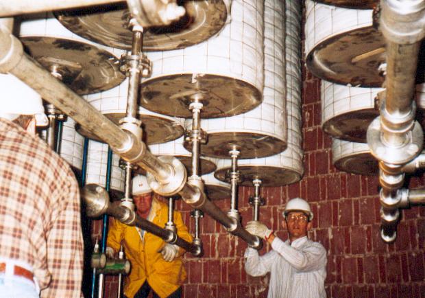 |
Candle Tubesheet The tubesheet supports the candle elements. The preferred method for mounting the candles is on a raised pedestal to provide for easy access to the mounting hardware. The tubesheet must be designed to support the weight of the candles when they are saturated with acid. The tubesheet must be rigid enough to stay flat. Any deformation may result in distortion of the mounting flange leading to leaks at the gasket. |
 |
| Examples of glass fibre beds attacked by fluorides. | Photos Courtesy of
Begg
Cousland Envirotec Limited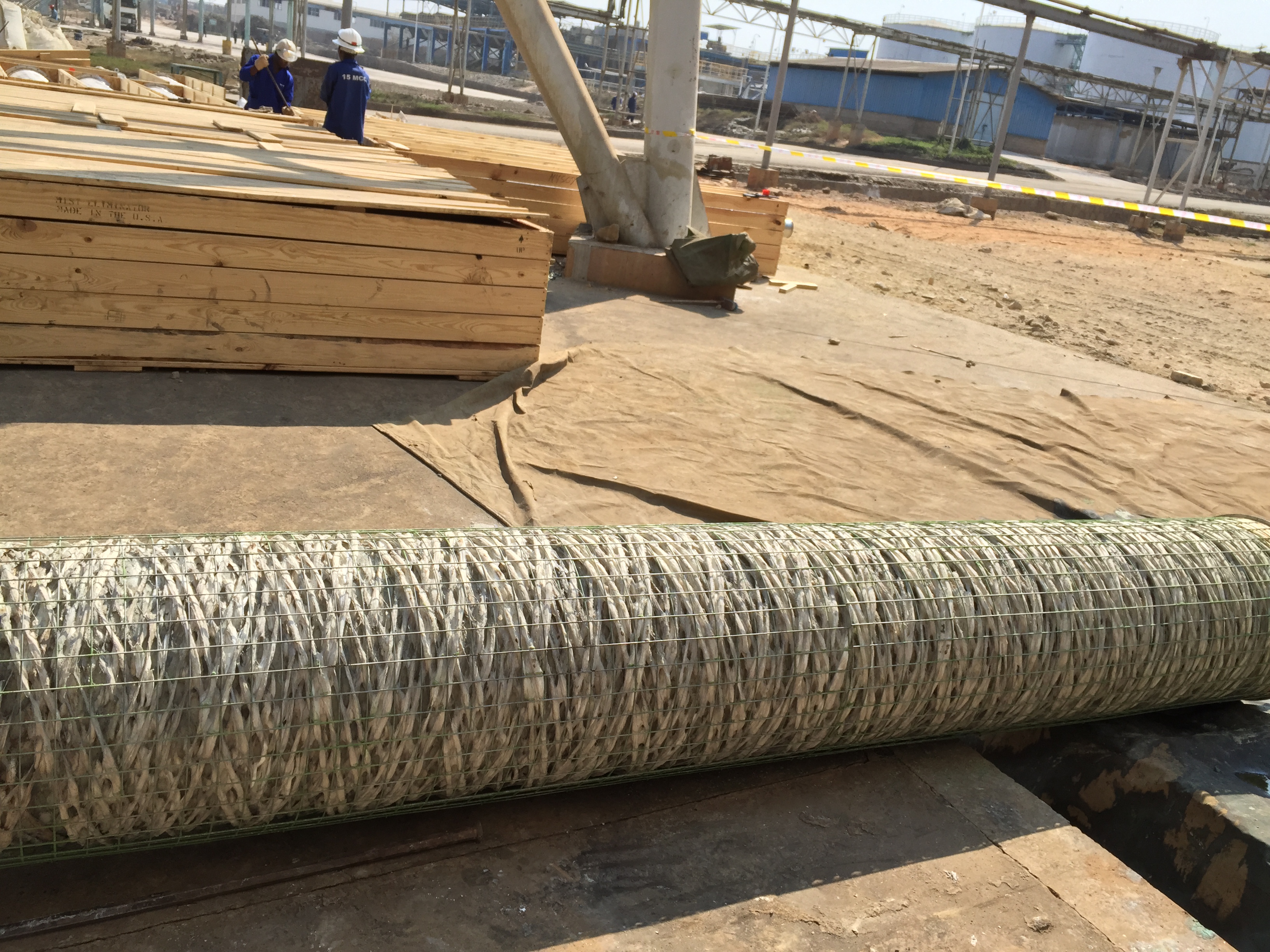
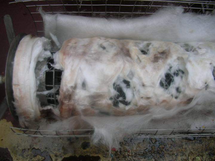
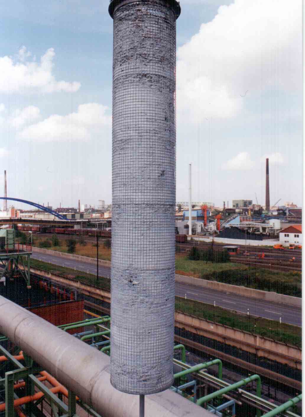
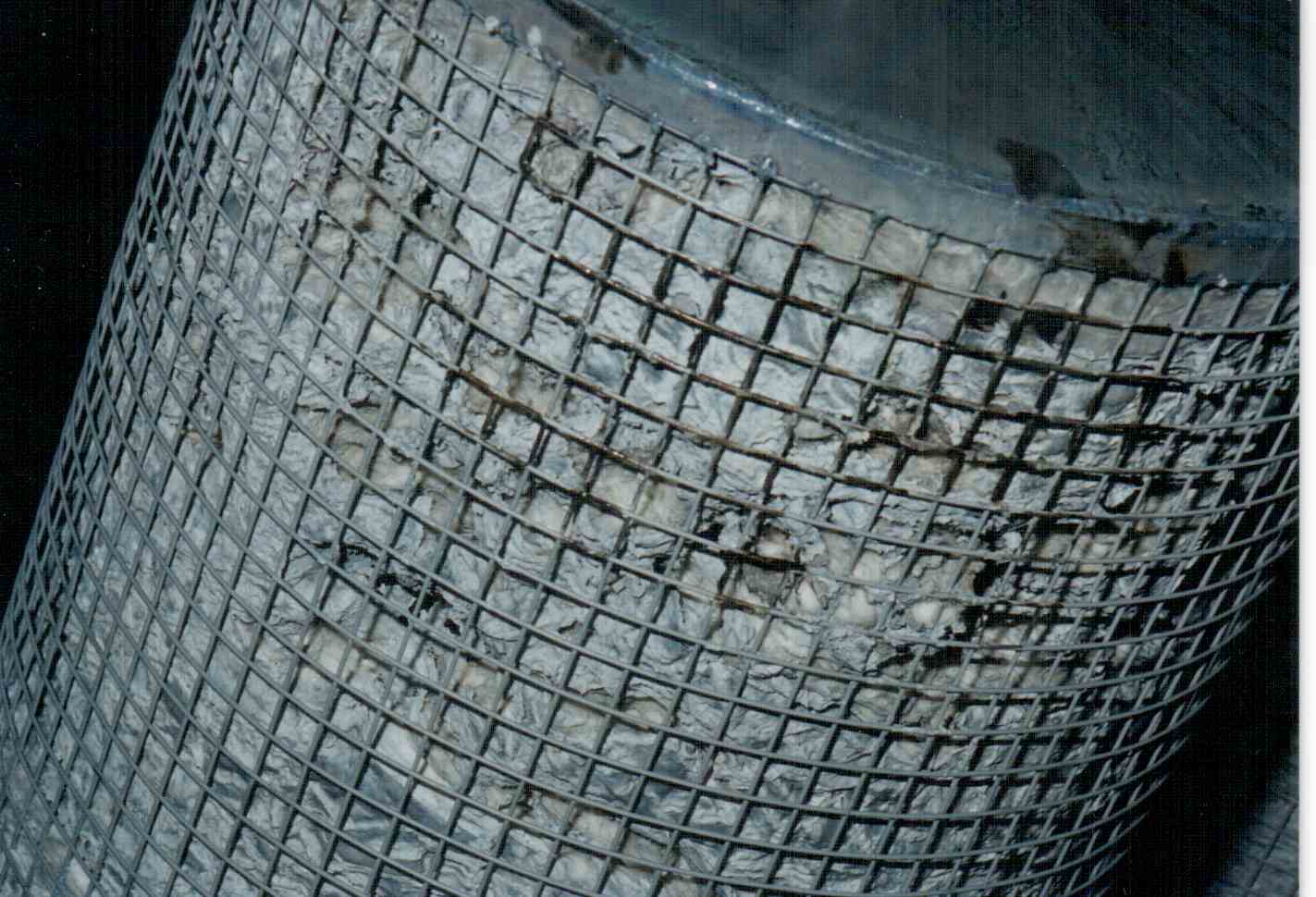 Photo Courtesy of Alvaro Stegman |
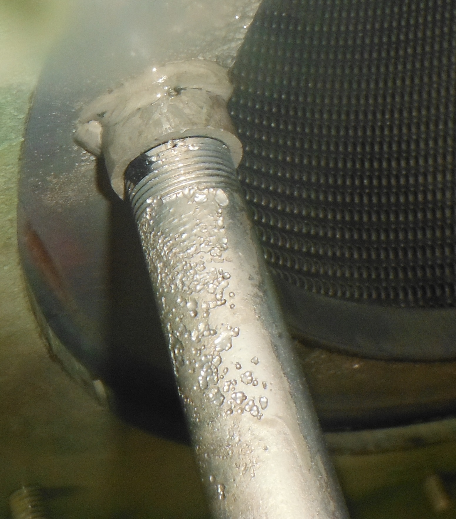
| Corrosion of the candle drain. Note pitting on the pipe. |
 |