|
||
| Sulphuric Acid on the WebTM | Technical Manual | DKL Engineering, Inc. |
Knowledge for the
Sulphuric Acid Industry
![]()
Sulphuric Acid on the Web
Introduction
General
Equipment Suppliers
Contractor
Instrumentation
Industry News
Maintenance
Acid
Traders
Organizations
Fabricators
Conferences
Used
Plants
Intellectual
Propoerty
Acid
Plant Database
Market
Information
Library
Technical Manual
Introduction
General
Definitions
Instrumentation
Plant Safety
Metallurgial
Processes
Metallurgical
Sulphur Burning
Acid Regeneration
Lead Chamber
Technology
Gas Cleaning
Contact
Strong Acid
Acid Storage
Loading/Unloading
Transportation
Sulphur
Systems
Liquid SO2
Boiler Feed Water
Steam Systems
Cooling Water
Effluent Treatment
Utilities
Construction
Maintenance
Inspection
Analytical Procedures
Materials of Construction
Corrosion
Properties
Vendor Data
DKL Engineering, Inc.
Handbook of Sulphuric Acid Manufacturing
Order
Form
Preface
Contents
Feedback
Sulphuric Acid
Decolourization
Order Form
Preface
Table of Contents
Process Engineering Data Sheets - PEDS
Order
Form
Table of Contents
Introduction
Bibliography of Sulphuric Acid Technology
Order Form
Preface
Contents

Storage/Loading/Unloading -
Storage Tanks - Erection
April
2, 2008
| Introduction | Associated Links |
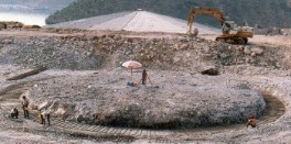
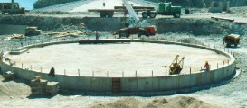
The following sequence of pictures illustrates the fabrication and erection of a large sulphuric acid storage tank.
| The foundation is excavated and a mudcoat is applied before rebar for the ring wall is laid. |
 |
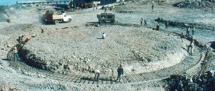
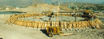
| Rebar being laid to form the tank foundation ring wall. |
 |
| More rebar being added with the start of the formwork. |
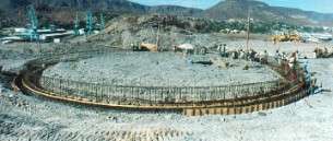 |
| Rebar and formwork completed. |
 |
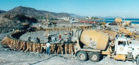
| Concrete being poured into formwork |
 |
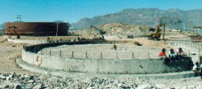
| Formwork has been stripped away revealing foundation ring wall. Interior of ring wall being backfilled. |
 |
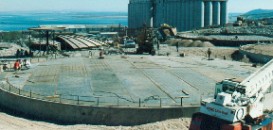
| Backfill, compacting and leveling of base complete. |
 |
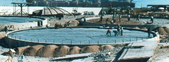
| Impervious liner applied over compacted base. The liner will direct and liquid towards the edge of the foundation. |
 |
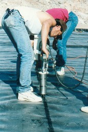
| Sealing between the sections of liner. |
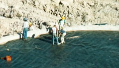 |
| Sealing between the sections of liner. |
 |
| The floor plates are welded and placed onto the foundation. |
 |
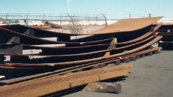
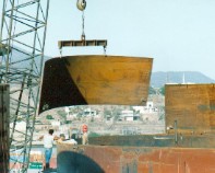
| The tank wall arrives as rolled plate. |
 |
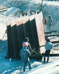
| Plates are positioned ready to be lifted and welded to form the wall of the tank. |
 |
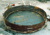
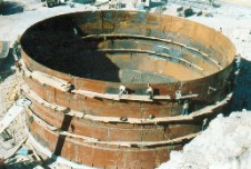
| First course of tank wall is completed. |
 |
| Plate being lifted into position to form the next course. |
 |
| Plate being positioned for welding. |
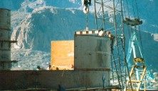 |
| Second course of tank wall complete. |
 |
| Roof sections as delivered to site. |
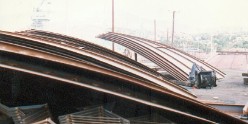 |
| Welding of roof sections into large sections. |
 |
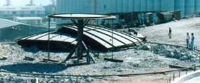
| Jig designed to aid in the fabrication of the roof. Center structure support middle of the roof while outer ring hold outer edge of roof. |
 |
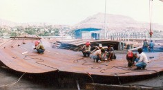
| View of roof jig from above. |
 |
| Partially completed roof section still on jig. |
 |
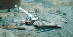
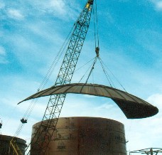
| Lifting of roof section. |
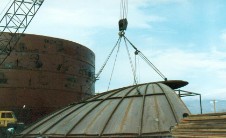 |
| Lifting of roof section. |
 |
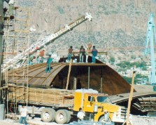
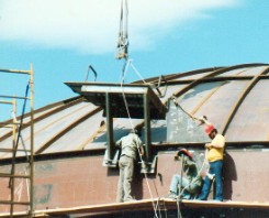
| Placement of roof section on top of tank. |
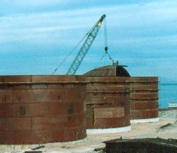 |
| Roof section on top of tank. |
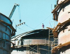 |
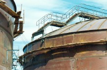
| Once the roof is complete, platforms, ladders and other attachments are added. |
 |
| Installation of access stairs and platforms |
 |
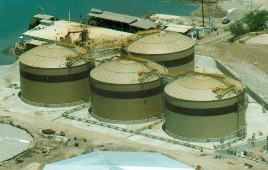
| Completed tank farm. |
 |